Activities Manual for Programmable Logic Controllers
5th Edition
ISBN: 9781259679568
Author: Petruzella, Frank
Publisher: MCGRAW-HILL HIGHER EDUCATION
expand_more
expand_more
format_list_bulleted
Concept explainers
Question
Chapter 6, Problem 3P
Program Plan Intro
Ladder logic program:
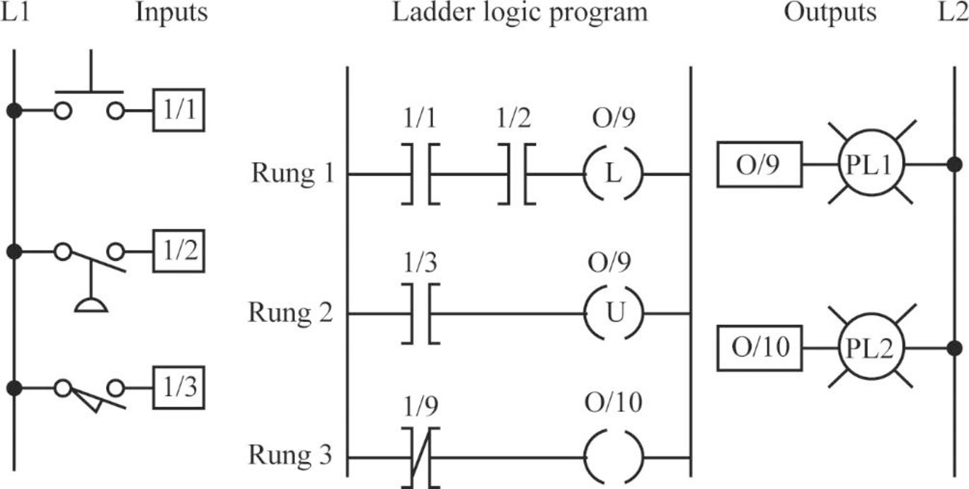
The above ladder logic program includes three inputs namely, I/1, I/2 and I/3, three rungs namely, Rung 1, Rung 2 and Rung 3, two pilot lights namely, PL1 and PL2 and two outputs namely, O/9 and O/10.
Explanation of Solution
b.
Condition for unlatch rung 2:
- When the input I/3 is set as true or ON state, the unlatch rung 2 is termed as active or in true state...
Explanation of Solution
c.
Condition for rung 3:
- When the input O/9 in Rung 3 is set as zero or low, the rung 3 is termed as active.
- When the input I/3 in Rung 2 is set as true, the output of Rung 2 will be reset as zero...
Explanation of Solution
d.
State of Pilot Light PL1:
- The ON state of pilot light PL1 represents that the output bit O/9 is in high state.
- This can be occurred when the relay in latched state is set to the bit 1...
Explanation of Solution
e.
State of Pilot Light PL2:
- The ON state of pilot light PL2 represents that the input bit I/3 is true in Rung 2...
Explanation of Solution
f.
Pilot Light used when the power is restored:
AC power is removed and restored through the circuit, the relay retains to its original state, n...
Explanation of Solution
g.
Inputs required for unlatched state:
- The relay is in latched state and the inputs I/1, I/2 and I/3 are false.
- To convert the relay state from latched to unlatched,...
Explanation of Solution
h.
State of the relay:
- The Programmable Logic Controller (PLC) executes the instructions according to top to bottom approach.
- When the closed instructions at I/1, I/2 and I/3 are termed...
Expert Solution & Answer
Want to see the full answer?
Check out a sample textbook solution
Students have asked these similar questions
In a chemical factory, a chemical is stored in three different tanks. A level
sensor in each tank produces a positive input voltage (+24V) when the level of
chemical in the tank drops below a specified point. Ladder logic will monitor
the chemical level in each tank and indicate an alarm condition when the level
in any two of the tanks drops below a specified point.
Develop a Truth Table, the resulting Boolean Expression and ladder logic in
its simplest form. Explain your method of Boolean simplification.
Inputs Required:
Tank 1 sensor
Tank 2 sensor
(X0)
(X1)
(X2)
Tank 3 sensor
Outputs Required:
(YO)
Alarm
A given room has two push-button switches S1 and S2 that are used to control a light bulb (e.g., one switch near each door of a room with 2 doors) as shown in below. You are to design a logic circuit so that the bulb can be controlled (essentially, toggled) by either switch.a. Write down the above scenario in an IF-THEN condition format b. Develop a truth table for the above case c. Develop a minimized Boolean function in SOP form
This is the question:
Suppose that we want to synthesize a circuit that has two switches x and y. The required functional behavior of the circuit is that the output must be equal to 0 if switch x is opened (x=0 ) and y is closed (y=1); otherwise the output must be 1.
My friend sent me the answer which I will attach but I have no idea what is going on .. can someone please explain in detail?
Chapter 6 Solutions
Activities Manual for Programmable Logic Controllers
Ch. 6 - Prob. 1RQCh. 6 - Prob. 2RQCh. 6 - Prob. 3RQCh. 6 - Prob. 4RQCh. 6 - Prob. 5RQCh. 6 - Prob. 6RQCh. 6 - Prob. 7RQCh. 6 - Prob. 8RQCh. 6 - What do the abbreviations NO and NC represent when...Ch. 6 - Prob. 10RQ
Ch. 6 - Prob. 11RQCh. 6 - Prob. 12RQCh. 6 - Compare the operation of a photovoltaic solar cell...Ch. 6 - What are the two basic components of a...Ch. 6 - Prob. 15RQCh. 6 - Give an explanation of how a scanner and a decoder...Ch. 6 - Prob. 17RQCh. 6 - Prob. 18RQCh. 6 - Prob. 19RQCh. 6 - Prob. 20RQCh. 6 - Prob. 21RQCh. 6 - Prob. 22RQCh. 6 - Prob. 23RQCh. 6 - Prob. 24RQCh. 6 - Prob. 25RQCh. 6 - Prob. 26RQCh. 6 - Prob. 27RQCh. 6 - Prob. 28RQCh. 6 - Prob. 29RQCh. 6 - Prob. 30RQCh. 6 - Prob. 31RQCh. 6 - Prob. 32RQCh. 6 - Prob. 33RQCh. 6 - Prob. 1PCh. 6 - Prob. 2PCh. 6 - Prob. 3PCh. 6 - Prob. 4PCh. 6 - Design a PLC program and prepare a typical I/O...Ch. 6 - Prob. 6PCh. 6 - Prob. 7PCh. 6 - Prob. 8P
Knowledge Booster


Learn more about
Need a deep-dive on the concept behind this application? Look no further. Learn more about this topic, computer-science and related others by exploring similar questions and additional content below.Similar questions
- Construct a basic stop/start seal-in circuit. Energize an internal relay to seal-in (latch) the circuit. write the circuit in both Ladder Logic and Function Block Diagram (FBD). Hardware setup: Input 1 - Normally closed stop pushbutton, Input 2 - Normally open start pushbutton. Output 1 - A Red light to indicate the circuit is not energized. Output 2 - A Green light to indicate the circuit is energized. Label all inputs and outputs in the plc program. Write the program in both ladder and function block diagram (FBD).arrow_forward1. The following expression uses an XOR gate. Recall that XOR is a combination of AND, OR and NOT gates. Remember that XOR is the lowest order of operator precedence. F = X * YOY+Z a. Draw the circuit as is with the XOR gate. b. Rewrite the expression replacing the XOR with its equivalent AND/OR/NOT gates. c. Draw the circuit for the revised expression in part b. d. How many total gates are used in your circuit for part a and how many for part b/c? Note that a NOR as 2 gates, an OR and then a NOT.arrow_forwardWhich of the following logic functions is implemented by the given circuit? (Hint: build a truth table of this MUX) a) f(A,B,C,D) = Σm(2,5,9,10,11,12,13,15)b) f(A,B,C,D) = Σm(0,7,8,10,11,13,14,15)c) f(A,B,C,D) = Σm(3,4,9,10,11,12,13,15)d) f(A,B,C,D) = Σm(3,5,6,7,8,12,13,15)e) f(A,B,C,D) = Σm(1,6,9,10,11,12,14,15)arrow_forward
- C1. Consider the designing of a synchronous circuit to detect the sequence 0110. The circuit has a single input x, and a single output z. The output is logic-l whenever the input sequence 0110 is detected, logic-0 otherwise. Note that overlapping sequences are allowed. Answer the following questions: a. Complete the following state diagram of the circuit: 1 so s1 S2 S3 S4 b. Draw and fill the state table of the circuit. c. Write the equations of the state variables and the output Z.arrow_forwardAO- For the above given logic circuit, the output Y value is =1 when the inputs of A, B, and C are a. None of these O b. A=1, B=1, C=1 O c. A=1, B=1, C=0 O d. A=1, B=0, C=1arrow_forward5. Consider the circuit below: A- B- C- a. Write the Boolean expression modeled by the circuit. Above. Use Boolean Algebra notation: A, (for not A); AB (for A and B), A + B (for A or B), A Ð B (A xor B), etc. b. Evaluate the output of each gate, including the final gate, given that A= 1, B=1 and C=1 Write your evaluation of each gate above each gate and include a screen shotarrow_forward
- Question 2: A combinational circuit has 4 inputs (A, B, C, D) and 1 output (F). ABCD represent a majority function. The output of the majority function is equal to 1 if the input variables have more 1's than O's, otherwise the output is 0. a. Construct the truth table of the required circuit. b. Implement the minimized expression of F using 3-level all NAND gate circuit. Implement a 2-1Multiplexer using three-state buffers.arrow_forward2. Consider the circuit below. a. Write the Boolean expression for output F in terms of A, B and C. b. Construct a truth table for the circuit with A as MSB and C as LSB. c. Write the Canonical SOP and POS forms for output F. A B C 3. Draw the logic circuit represented by the expression F(A, B) = AB using no more than 5 units of 2-input NAND gate and write the corresponding Boolean expression.arrow_forwardCreate a non-abbreviated logic diagram for the following Boolean Expressions. You can use all gates. (a XOR b + b’ XOR c’)arrow_forward
- 2- Write the Boolean equations and draw the logic diagram of the circuit whose outputs are defined by the following truth table: A B F1 F2 1 1 1 1 1 1 1 1 1 1 1 1 1 1 1 1 1 1 1arrow_forwardQuestion 1 Implement the following logic functions using BJTs. Use the S-Model. Both input and output should be voltage signals OUT= A.B + C OUT = A.B + A.Barrow_forwardA5. Examine the logic circuit in Fig. 5.2, and write the Boolean expression for output G. A7. Construct the K-map to simplify G. G= CD 00 01 11 10 AB 00 01 11 10 A8. Write the Boolean expression of G by using the K-map. G= D A9. Draw the logic diagram of the simplified expression in the space provided below. Fig. 5.2 A6. Connect the circuit as shown in Fig. 5.2, set binary switches to each set of input values and record the corresponding outputs in Table 5.2. Table 5.2 A В D G A10. Construct the simplified expression by using only NAND gates. Design and draw the NAND gates connection diagram of simplified function 1 1 1 1 1 1 A11. Construct the circuit diagram obtained in A10 and set binary switches to each set of input values as in Table 5.2. 1 1 Does the circuit constructed in A10 give the same outputs of circuit in Fig. 5.2? 1 1 1 1 1 1 1 1 1 1 1arrow_forward
arrow_back_ios
SEE MORE QUESTIONS
arrow_forward_ios
Recommended textbooks for you
 Database System ConceptsComputer ScienceISBN:9780078022159Author:Abraham Silberschatz Professor, Henry F. Korth, S. SudarshanPublisher:McGraw-Hill Education
 Starting Out with Python (4th Edition)Computer ScienceISBN:9780134444321Author:Tony GaddisPublisher:PEARSON
 Digital Fundamentals (11th Edition)Computer ScienceISBN:9780132737968Author:Thomas L. FloydPublisher:PEARSON
 C How to Program (8th Edition)Computer ScienceISBN:9780133976892Author:Paul J. Deitel, Harvey DeitelPublisher:PEARSON
 Database Systems: Design, Implementation, & Manag...Computer ScienceISBN:9781337627900Author:Carlos Coronel, Steven MorrisPublisher:Cengage Learning
 Programmable Logic ControllersComputer ScienceISBN:9780073373843Author:Frank D. PetruzellaPublisher:McGraw-Hill Education
Database System Concepts
Computer Science
ISBN:9780078022159
Author:Abraham Silberschatz Professor, Henry F. Korth, S. Sudarshan
Publisher:McGraw-Hill Education
Starting Out with Python (4th Edition)
Computer Science
ISBN:9780134444321
Author:Tony Gaddis
Publisher:PEARSON
Digital Fundamentals (11th Edition)
Computer Science
ISBN:9780132737968
Author:Thomas L. Floyd
Publisher:PEARSON
C How to Program (8th Edition)
Computer Science
ISBN:9780133976892
Author:Paul J. Deitel, Harvey Deitel
Publisher:PEARSON
Database Systems: Design, Implementation, & Manag...
Computer Science
ISBN:9781337627900
Author:Carlos Coronel, Steven Morris
Publisher:Cengage Learning
Programmable Logic Controllers
Computer Science
ISBN:9780073373843
Author:Frank D. Petruzella
Publisher:McGraw-Hill Education