
Concept explainers
Videos
6-37* to 6-46* For the problem specified in the table, build upon the results of the original problem to determine the minimum factor of safety for fatigue based on infinite life, using the modified Goodman criterion. The shaft rotates at a constant speed, has a constant diameter, and is made from cold-drawn AISI 1018 steel.
| Problem Number | Original Problem, Page Number |
| 6-45* | 3–77, 153 |
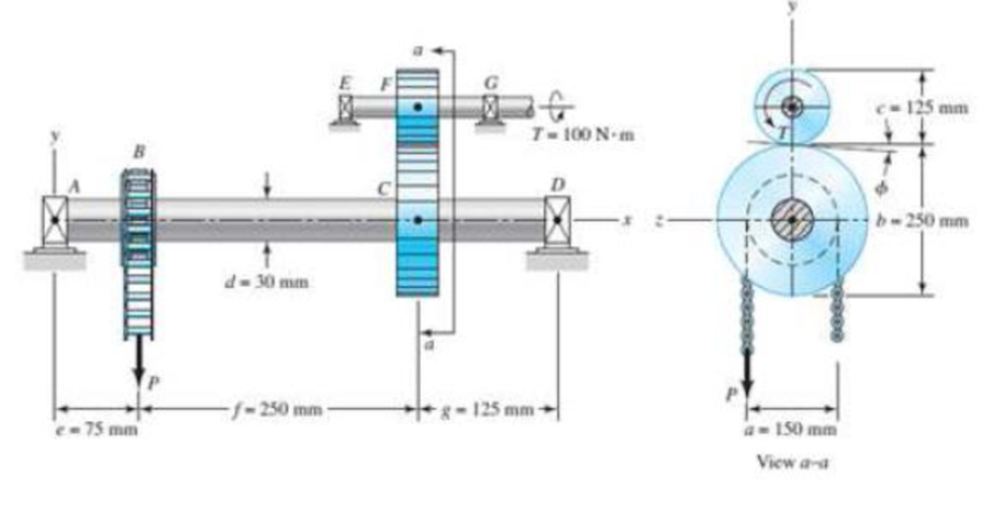
3-77 A torque T = 100 N · m is applied to the shaft EFG, which is running at constant speed and contains gear F. Gear F transmits torque to shaft ABCD through gear C, which drives the chain sprocket at B, transmitting a force P as shown. Sprocket B, gear C, and gear F have pitch diameters of a = 150, b = 250, and c = 125 mm, respectively. The contact force between the gears is transmitted through the pressure angle ϕ = 20°. Assuming no frictional losses and considering the bearings at A, D, E, and G to be simple supports, locate the point on shaft ABCD that contains the maximum tensile bending and maximum torsional shear stresses. Combine these stresses and determine the maximum principal normal and shear stresses in the shaft.
Want to see the full answer?
Check out a sample textbook solution
Chapter 6 Solutions
Shigley's Mechanical Engineering Design (McGraw-Hill Series in Mechanical Engineering)


- Three round, copper alloy bars having the same length L but different shapes are shown, in the figure. The first bar has a diameter d over its entire length, the second has a diameter d over one-fifth of its length, and the third has a diameter d over one-fifteenth of its length. Elsewhere, the second and third bars have a diameter Id. All three bars are subjected to the same axial load P. Use the following numerical data: P = 1400 kN, L = 5m,d= 80 mm, E= 110 GPa. and v = 0.33. (a) Find the change in length of each bar. (b) Find the change in volume of each bar.arrow_forwardA motor driving a solid circular steel shaft with diameter d = 1.5 in, transmits 50 hp to a gear at B, The allowable shear stress in the steel is 6000 psi. Calculate the required speed of rotation (number of revolutions per minute) so that the shear stress in the shaft does not exceed the allowable limit.arrow_forwardTwo sections of steel drill pipe, joined by bolted flange plates at Ä are being tested to assess the adequacy of both the pipes. In the test, the pipe structure is fixed at A, a concentrated torque of 500 kN - m is applied at x = 0.5 m, and uniformly distributed torque intensity t1= 250 kN m/m is applied on pipe BC. Both pipes have the same inner diameter = 200 mm. Pipe AB has thickness tAB=15 mm, while pipe BC has thickness TBC= 12 mm. Find the maximum shear stress and maximum twist of the pipe and their locations along the pipe. Assume G = 75 GPa.arrow_forward
- A tubular shaft being designed for use on a construction site must transmit 120 kW at 1,75 Hz, The inside diameter of the shaft is to be one-half of the outside diameter. If the allowable shear stress in the shaft is 45 MPa, what is the minimum required outside diameter d?arrow_forwardThe figure shows a section of a shaft made of annealed steel with yield strength of 600 MPa and ultimate tensile strength of 700 MPa. Diameters of the shaft are D=30 mm and d=20 mm. Fillet radius of the shoulder section is 2.5 mm. The shaft is rotating and subjected to steady bending moment of M=51 Nm, steady torsion of T=58 Nm and steady axial load of F=14 kN. The operating temperature of the shaft is 20 ᵒC and reliability is 99%. The shaft has ground surface. Calculate the alternating component of the normal stress (in MPa). (If there is no alternating component of the normal stress, enter "0" in the answer box)arrow_forwardThe shaft in the figure is mounted with a gear wheel key. Shaft material 42CrMo4 The weight of the gear on the shaft is 0.9 kg, dimension, surface and notch factors KbK / Kç = 0.83, shaft speed n = 1120 rpm, shaft transmitted power 7.5 kW, force on shaft Fn = F = 2680 N Since the desired safety coefficient is Ssafe = 2; Check the safety of the shaftarrow_forward
- A Steel shaft is subjected to an end thrust producing a stress of 90 MPa and the minimum shearing stress on the surface arising from torsion is 60 MPa .The yield point stress of the material in simple tension was found to be 300 MPa. calculate the factor of safety of the shaft according to the following theory 1)maximum shear stress theoryarrow_forwardA certain steel shafting material has an ultimate strength of 93 ksi, a notch radius of 0.25 inch, and a stress concentration factor of 2.5 at its pitch. Determine the fatigue-strength reduction factor for a life of 166,077 cycles onlyarrow_forwardA rotating shaft of 40×4 mm AISI 1018 cold-drawn steel tubing has a 6 mm diameter hole drilled transversely through it. Estimate the factor of safety guarding against fatigue and static failures using the Gerber and Langer failure criteria for the following loading conditions: a. The shaft is subjected to a completely reversed torque of 120 N.m in phase with a completely reversed bending moment of 150 N.m. b. The shaft is subjected to a pulsating torque fluctuating from 20 to 160 N.m and as steady bending moment of 150 N.m.arrow_forward
- An input shaft of a gearbox with motor power P = 7 kW and rotation number n = 1300 rpm. The diameter of an input shaft is d = 20 mm and its material is 16MnCr5. A force of F = 2800 N forces the shaft due to the operation of a gear wheel connected with a wedge on the input shaft. The distances of the gear from the bearings are given as L₁ = 40 mm and L2 = 60 mm. In the most dangerous section, you are required to check the strength according to the S = 3 safety factor. If the section is unsafe in terms of strength, what changes would you make in the design to make it safe? (The surface of the spindle is machined as fine chips, reliability poor Kg = 1.).arrow_forwardThe figure shows a shaft mounted in bearings at A and D and having pulleys at B and C. The forces shown acting on the pulley surfaces represent the belt tensions. The shaft is to be made of AISI 1035 CD steel. The shaft is rotating at speed of 1000 rpm. Find the minimum factor of safety for fatigue based on infinite life. If the life is not infinite, estimate the number of cycles. Be sure to check for yielding. Take shaft diameter to be 1.5 inches.arrow_forwardThe cold-drawn AISI 1040 Q&T at 205 ◦C steel bar shown in the figure is subjected to a completely reversed axial load fluctuating between 28 kN in compression to 28 kN in tension. Estimate the fatigue factor of safety based on achieving infinite life, and the yielding factor of safety for the following cases. If infinite life is not predicted, estimate the number of cycles to failure.a) for the part given in Fig 2(a) and b) for the part given in Fig. 2 (b) using the same dimensions (W=25mm, r=3mm, the thickness of 10 mm)arrow_forward
 Mechanics of Materials (MindTap Course List)Mechanical EngineeringISBN:9781337093347Author:Barry J. Goodno, James M. GerePublisher:Cengage Learning