
Shigley's Mechanical Engineering Design (McGraw-Hill Series in Mechanical Engineering)
10th Edition
ISBN: 9780073398204
Author: Richard G Budynas, Keith J Nisbett
Publisher: McGraw-Hill Education
expand_more
expand_more
format_list_bulleted
Concept explainers
Videos
Textbook Question
Chapter 6, Problem 54P
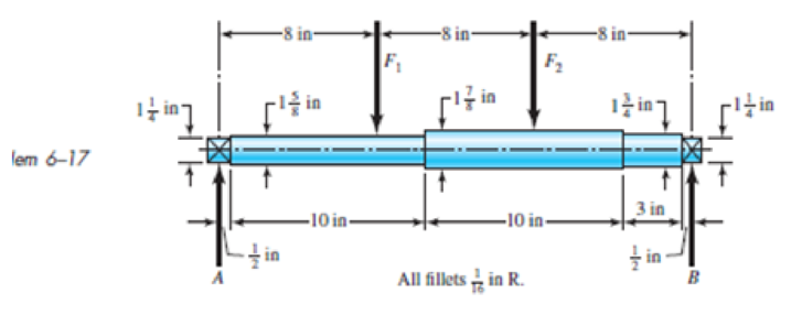
Solve Prob. 6-17 except include a steady torque of 2500 lbf · in being transmitted through the shaft between the points of application of the forces.
6-17 The shaft shown in the figure is machined from AIS1 1040 CD steel. The shaft rotates at 1600 rpm and is supported in rolling bearings at A and B. The applied forces are F1 = 2500 Ibf and F2 = 1000 Ibf. Determine the minimum fatigue factor of safety based on achieving infinite life. If infinite life is not predicted, estimate the number of cycles to failure. Also check for yielding.
Expert Solution & Answer
Want to see the full answer?
Check out a sample textbook solution
Students have asked these similar questions
The solid steel rotating shaft in the figure is supported at B and C, and is driven by a gear, not seen, which is linked to spur gear D which has a pitch diameter of 150 mm. The drive gear force F acts at a pressure angle of 20 degrees. The shaft transmits a torque to point A of Ta-350 N.m. The properties of machined steel shaft are Sy-420 MPa and Sut-560MPa. Use a safety factor of 2.5 and determine the minimum allowable diameter in section B and C. Assume sharp felt radii at the bearing shoulders to estimate the stress concentration factors.Explain.
The shaft shown in the figure is machined from AISI 1040 CD steel. The shaft rotates at 1600 rpm and is supported in rolling bearings at A and B. The applied forces are F1 = 1600 lbf and F2 = 640 lbf. A steady torque of 1600 lbf·in is being transmitted through the shaft between the points of application of the forces.
A brass shaft AC (G =5.6 *10^3 ksi) is subjected to torsional loads at sections B and C, as shown in Fig. P4.5-2. The outside diameter of the shaft is d1 = do2 =d = 1.25 in. A central hole of diameter di2 = 0.75 in. has been drilled from C to B, creating a two-segment shaft with lengths L1 = L2 =10 in. If the two applied torques are TB = 400 lb in. and TC =200 lb in., respectively, (a) determine the maximum shear stress in the two-segment shaft, and (b) determine the angle of rotation fC (in radians) at the end of the shaft. (Note that both torque TB and TC are pos- itive, meaning that both torques act in the sense shown in Fig. P4.5-2.)
Chapter 6 Solutions
Shigley's Mechanical Engineering Design (McGraw-Hill Series in Mechanical Engineering)
Ch. 6 - A 10-mm steel drill rod was heat-treated and...Ch. 6 - Prob. 2PCh. 6 - A steel rotating-beam test specimen has an...Ch. 6 - A steel rotating-beam test specimen has an...Ch. 6 - A steel rotating-beam test specimen has an...Ch. 6 - Repeat Prob. 6-5 with the specimen having an...Ch. 6 - A steel rotating-beam test specimen has an...Ch. 6 - Derive Eq. (6-17). Rearrange the equation to solve...Ch. 6 - For the interval 103 N 106 cycles, develop an...Ch. 6 - Estimate the endurance strength of a...
Ch. 6 - Two steels are being considered for manufacture of...Ch. 6 - A 1-in-diamctcr solid round bar has a groove...Ch. 6 - A solid square rod is cantilevered at one end. The...Ch. 6 - A rectangular bar is cut from an AISI 1020...Ch. 6 - A solid round bar with diameter of 2 in has a...Ch. 6 - The rotating shaft shown in the figure is machined...Ch. 6 - The shaft shown in the figure is machined from...Ch. 6 - Solve Prob. 6-17 except with forces F1 = 1200 lbf...Ch. 6 - Bearing reactions R1 and R2 are exerted on the...Ch. 6 - A bar of steel has the minimum properties Se = 40...Ch. 6 - Repeat Prob. 6-20 but with a steady torsional...Ch. 6 - Repeat Prob. 6-20 but with a steady torsional...Ch. 6 - Repeat Prob. 6-20 but with an alternating...Ch. 6 - A bar of steel has the minimum properties Se = 40...Ch. 6 - The cold-drawn AISI KUO steel bar shown in the...Ch. 6 - Repeat Prob. 6-25 for a load that fluctuates from...Ch. 6 - An M14 2 hex-head bolt with a nut is used to...Ch. 6 - The figure shows a formed round-wire cantilever...Ch. 6 - The figure is a drawing of a 4- by 20-mm latching...Ch. 6 - The figure shows the free-body diagram of a...Ch. 6 - Solve Prob. 6-30 except let w1 = 2.5 in. w2 = l.5...Ch. 6 - For the part in Prob. 630, recommend a fillet...Ch. 6 - Prob. 33PCh. 6 - Prob. 34PCh. 6 - A part is loaded with a combination of bending,...Ch. 6 - Repeat the requirements of Prob. 6-35 with the...Ch. 6 - 6-37 to 6-46For the problem specified in the build...Ch. 6 - 6-37 to 6-46For the problem specified in the build...Ch. 6 - 637 to 646 For the problem specified in the table,...Ch. 6 - For the problem specified in the table, build upon...Ch. 6 - 6-37 to 6-46 For the problem specified in the...Ch. 6 - 6-37 to 6-46 For the problem specified in the...Ch. 6 - 6-37 to 6-46 For the problem specified in the...Ch. 6 - Problem Number Original Problem, Page Number 637...Ch. 6 - 6-37 to 6-46 For the problem specified in the...Ch. 6 - 6-37 to 6-46 For the problem specified in the...Ch. 6 - 6-47 to 6-50 For the problem specified in the...Ch. 6 - 6-47 to 6-50 For the problem specified in the...Ch. 6 - Prob. 49PCh. 6 - Prob. 50PCh. 6 - 6-51 to 6-53 For the problem specified in the...Ch. 6 - 6-51 to 6-53 For the problem specified in the...Ch. 6 - 6-51 to 6-53 For the problem specified in the...Ch. 6 - Solve Prob. 6-17 except include a steady torque of...Ch. 6 - Solve Prob. 618 except include a steady torque of...Ch. 6 - In the figure shown, shaft A, made of AISI 1020...Ch. 6 - A schematic of a clutch-testing machine is shown....Ch. 6 - For the clutch of Prob. 657, the external load P...Ch. 6 - A flat leaf spring has fluctuating stress of max =...Ch. 6 - A rotating-beam specimen with an endurance limit...Ch. 6 - A machine part will be cycled at 350 MPa for 5...Ch. 6 - The material properties of a machine part are Sut...Ch. 6 - Repeat Prob. 662 using the Goodman criterion....
Knowledge Booster


Learn more about
Need a deep-dive on the concept behind this application? Look no further. Learn more about this topic, mechanical-engineering and related others by exploring similar questions and additional content below.Similar questions
- What is the maximum power that can be delivered by a hollow propeller shaft (outside diameter 50 mm, inside diameter 40 mm, and shear modulus of elasticity 80 GPa) turning at 600 rpm if the allowable shear stress is 100 MPa and the allowable rate of twist is 3.0°/m?arrow_forwardThe stepped shaft shown in the figure is required to transmit 600 kW of power at 400 rpm. The shaft has a full quarter-circular fillet, and the smaller diameter D1= 100 mm. If the allowable shear stress at the stress concentration is 100 MPa, at what diameter will this stress be reached? Is this diameter an upper or a lower limit on the value of D2?arrow_forwardThe steel axle of a large winch on an ocean liner is subjected to a torque of 1.65 kN · m (see figure). What is the minimum required diameter dminif the allowable shear stress is 48 M Pa and the allowable rate of twist is 0.75º/m? (Assume that the shear modulus of elasticity is 80 G Pa.) Repeat part (a) if the shaft is now hollow with an inner diameter of 5d/8, Compare dminvalues to corresponding values from part (a)arrow_forward
- A crank arm consists of a solid segment of length bxand diameter rf, a segment of length bltand a segment of length byas shown in the figure. Two loads P act as shown: one parallel to — vand another parallel to —y. Each load P equals 1.2 kN. The crankshaft dimensions are A] = 75 mm, fr> = 125 mm, and b3= 35 mm. The diameter of the upper shaft isd = 22 mm, (a) Determine the maximum tensile, compressive, and shear stresses at point A, which is located on the surface of the shaft at the z axis. (b) Determine the maximum tensile, compressive, and shear stresses at point B, which is located on the surface of the shaft at the y axisarrow_forwardA magnesium-alloy wire of diameter d = 4mm and length L rotates inside a flexible tube in order to open or close a switch from a remote location (see figure). A torque Tis applied manually (either clockwise or counterclockwise) at end 5, thus twisting the wire inside the tube. At the other end A, the rotation of the wire operates a handle that opens or closes the switch. A torque T0 = 0.2 N · m is required to operate the switch. The torsional stiffness of the tube, combined with friction between the tube and the wire, induces a distributed torque of constant intensity t = 0.04N m/m (torque per unit distance) acting along the entire length of the wire. (a) If the allowable shear stress in the wire is T allow = 30 MPa, what is the longest permissible length Lmaxof the wire?arrow_forwardThe composite shaft shown in the figure is manufactured by shrink-Fitting a steel sleeve over a brass core so that the two parts act as a single solid bar in torsion. The outer diameters of the two parts are dY= 40 mm for the brass core and d2= 50 mm for the steel sleeve. The shear moduli of elasticity are Gb= 36 GPa for the brass and Gs= 80 GPa for the steel. (a) Assuming that the allowable shear stresses in the brass and steel are rb= 48 MPa and ts= 80 MPa, respectively, determine the maximum permissible torque Tmax that may be applied to the shaft. (b) If the applied torque T = 2500 kN · m, find the required diameter d2so that allowable shear stress t3is reached in the steel.arrow_forward
- A tubular shaft being designed for use on a construction site must transmit 120 kW at 1,75 Hz, The inside diameter of the shaft is to be one-half of the outside diameter. If the allowable shear stress in the shaft is 45 MPa, what is the minimum required outside diameter d?arrow_forwardA propeller shaft for a small yacht is made of a solid steel bar 104 mm in diameter. The allowable stress in shear is 48 MPa, and the allowable rate of twist is 2.0° in 3.5 meters. (a) Assuming that the shear modulus of elasticity is G = 80 GPa, determine the maximum torque that can be applied to the shaft. (b) Repeat part (a) if the shaft is now hollow with an inner diameter of 5d18. Compare values to corresponding values from part (a).arrow_forwardA solid circular shaft AB of diameter d is fixed against rotation at both ends (sec figure), A circular disk is attached to the shaft at the location shown. What is the largest permissible angle of rotation 0max of the disk if the allowable shear stress in the shaft is Tallow? [Assume that a >b. Also, use Eqs. (3-50a and b) of Example 3-9 to obtain the reactive torques.]arrow_forward
- Two sections of steel drill pipe, joined by bolted flange plates at Ä are being tested to assess the adequacy of both the pipes. In the test, the pipe structure is fixed at A, a concentrated torque of 500 kN - m is applied at x = 0.5 m, and uniformly distributed torque intensity t1= 250 kN m/m is applied on pipe BC. Both pipes have the same inner diameter = 200 mm. Pipe AB has thickness tAB=15 mm, while pipe BC has thickness TBC= 12 mm. Find the maximum shear stress and maximum twist of the pipe and their locations along the pipe. Assume G = 75 GPa.arrow_forwardA steel punch consists of two shafts: upper shaft and lower shaft. Assume that the upper shaft has a diameter d1= 24 mm and the bottom shaft has a diameter d2= 16 mm. The punch is used to insert a hole in a 4 mm plate, as shown in the figure. If a force P - 70 kN is required to create the hole, what is the average shear stress in the plate and the average compressive stress in the upper and lower shaft of the punch?arrow_forwardA solid copper bar of circular cross section has length L = 1.25 m and shear modulus of elasticity G = 45 GPa. The bar is designed to carry a 250 N · m torque acting at the ends. If the allowable shear stress is 30 M Pa and the allowable angle of twist between the ends is 2.5°, what is the minimum required diameter?arrow_forward
arrow_back_ios
SEE MORE QUESTIONS
arrow_forward_ios
Recommended textbooks for you
 Mechanics of Materials (MindTap Course List)Mechanical EngineeringISBN:9781337093347Author:Barry J. Goodno, James M. GerePublisher:Cengage Learning
Mechanics of Materials (MindTap Course List)
Mechanical Engineering
ISBN:9781337093347
Author:Barry J. Goodno, James M. Gere
Publisher:Cengage Learning
Everything About COMBINED LOADING in 10 Minutes! Mechanics of Materials; Author: Less Boring Lectures;https://www.youtube.com/watch?v=N-PlI900hSg;License: Standard youtube license