
Concept explainers
Videos
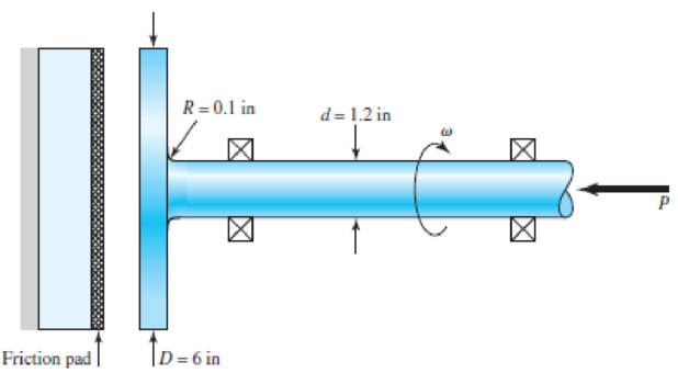
A schematic of a clutch-testing machine is shown. The steel shaft rotates at a constant speed ω. An axial load is applied to the shaft and is cycled from zero to P. The torque T induced by the clutch face onto the shaft is given by
where D and d are defined in the figure and f is the coefficient of friction of the clutch face. The shaft is machined with Sy = 120 kpsi and Sut = 145 kpsi. The theoretical stress-concentration factors for the fillet are 3.0 and 1.8 for the axial and torsional loading, respectively.
Assume the load variation P is synchronous with shaft rotation. With Sy = 0.3, find the maximum allowable load P such that the shaft will survive a minimum of 106 cycles with a factor of safety of 3. Use the modified Goodman criterion. Determine the corresponding factor of safety guarding against yielding.
Problem 6–57
Want to see the full answer?
Check out a sample textbook solution
Chapter 6 Solutions
Connect 1-semester Access Card For Shigley's Mechanical Engineering Design


- 8. Design a clamp coupling for transmitting 25 kW at 300 rpm. Allowable shear stresses in shaft and key are 50 MPa and 45 MPa, respectively. The number of bolts joining the two halves of muff is 4. The permissible tensile stress in the bolt is 70 MPa and the permissible crushing stress in the key is 90 MPa. The coeffi cient of friction between the muff of the CI and the shaft of steel is 0.20.arrow_forwardA single disc clutch with both sides effective is required for a vehicle. The power for initial estimation of the clutch is 100 kW at 4000 rpm. Determine the radial dimensions (inner and outer radius) and the actuating force (W). Base the design on the uniform wear assumption. Assume maximum pressure (pmax) as 1.6 MN/m2 and ?2?1= 1√2where ‘r2’ and ‘r1’ represent inner and outer radius of the friction surface. Take µ = 0.35. Find also the minimum pressure (pmin).arrow_forwardAn engine of a motor vehicle with a wheel diameter of 712 mm develops 50 kW at 2,000 rpm combined efficiencyof the differential and transmission is 75% with an over-all speed reduction to. 1 determine he torque to bedelivered by the clutch N-m.arrow_forward
- 6. Design a clamp coupling for transmitting 36 kW, at 200 rpm. Allowable shear stress in shaft is 45 MPa, allowable shear stress in key is 40 MPa, and allowable crushing stress in key is 90 MPa. The number of bolts joining the two halves is 4. The permissible tensile stress in bolts is 60 MPa. The coefficient of friction between the muff and shaft can be taken as 0.25arrow_forwardQ1) The mean diameter of the driving pulley for a vee-belt drive with two belts is 110 mm. The pulley groove angle is 40° and the drive transmits 4.4 kW at a speed of rotation of 1500 rev/min. The coefficient of friction between belt and pulley 0.32, and the angle of lap is 160°. Determine the driving torque and the maximum stress in the belt material if the cross-sectional area of each belt is 120 mm2.arrow_forwardThe corediameter of the double start square threaded screw having a pitch of 12mm is 50 mm. A load of 18kN is lifted through a distance of 180mm. Find the work done(in Joule)in lifting the loadand the efficiency of the screw, when 1. The load rotates with the screw, and 2. The load rests on the loose head which does not rotate with the screw. The external and internal diameter of the bearing surface of the loose head are 60 mm and 10 mmrespectively. The coefficient of friction for the screw is 0.11,whilefor the bearing surface is 0.13.arrow_forward
- A wagon weighing 5100 Kg moving at a speed of 8 km/h has to be brought to rest. Springs made of wire diameter 25mm with a Dm of 250mm and with 24 turns are available. Find the number of springs required in buffer to stop the wagon at a compression of 180mm. b)A close coiled helical spring is made of diameter wire 25mm. The spring index is 8. Findthe number of turns required and maximum allowable load if the allowable shear stress is100 MPa and elongation is limited to 40mm. [G=80 GPaarrow_forwardTwo parts of a machine, both made from steel, are held together by 7 equally-spaced M6 x 1.0 grade 8.8 bolts that are uniformly tightened to provide a total initial clamping force of 60 kN. What wrench torque is required to set the preload on these bolts? Assume a torque factor of 0.18 in your calculations. Express your answer in units of newton meters to a resolution of 0.1 N-m.arrow_forwardThe figure shows an internal rim-type brake having an inside rim diameter of 11in and a dimension R of 3.5 in. The shoes have a face width of 1.25 in. Find the braking torque and the maximum pressure for each shoe if the actuating force is 205 Ibf, the drum rotation is counterclockwise, and f=0.32. The maximum pressure on the right-hand shoe parp is [ 16.99] @ psi. The maximum pressure on the left-hand shoe pa| H is [100.813 | @ psi. The torque on the right-hand shoe Tgis [ .056 | @ kipin. The torque on the left-hand shoe T is [ .332| @ kipin. Total braking torque Tiotal s [-3887] @ Kip-in.arrow_forward
- Mechanical design A shaft with the following data: 1- The pulley (A) is 1000 mm in diameter and weight 300N. 2- The gear (B) pitch diameter is 600mm and weight -250N. 3- The pulley is keyed to the shaft at 400mm to the left of left hand bearing. 4-the distance between bearing C and B is 1250 mm. 5- The power is 20 kW at 750 rpm. 6- Tension ratio T1 / T2-2.5 7- The shaft d.livers power to a gear placed horizontally in front, the pressure angel of gear is 20. 8- The allowable shear stress is 70N / mm, kt-2 and km- 1.5. Determine: the diameter of shaftarrow_forwardAn input shaft of a gearbox with motor power P = 7 kW and rotation number n = 1300 rpm. The diameter of an input shaft is d = 20 mm and its material is 16MnCr5. A force of F = 2800 N forces the shaft due to the operation of a gear wheel connected with a wedge on the input shaft. The distances of the gear from the bearings are given as L₁ = 40 mm and L2 = 60 mm. In the most dangerous section, you are required to check the strength according to the S = 3 safety factor. If the section is unsafe in terms of strength, what changes would you make in the design to make it safe? (The surface of the spindle is machined as fine chips, reliability poor Kg = 1.).arrow_forwardPulleys A and B are separated by 450 mm. The shaft has a diameter of 40 mm and is made of steel with G=75GPa�=75GPa. Pulley A has a radius of 100 mm and pulley b has a radius of 150 mm. The belt on pulley A has a tension of 4 kN in the counter-clockwise direction and a tension of 10 kN in the clockwise direction. The belt on pulley B has a tension of 6 kN in the counter-clockwise direction and a tension of 2 kN in the clockwise direction. What is the angle of twist (in degrees) of pulley B relative to pulley A?arrow_forward
 Elements Of ElectromagneticsMechanical EngineeringISBN:9780190698614Author:Sadiku, Matthew N. O.Publisher:Oxford University Press
 Mechanics of Materials (10th Edition)Mechanical EngineeringISBN:9780134319650Author:Russell C. HibbelerPublisher:PEARSON
 Thermodynamics: An Engineering ApproachMechanical EngineeringISBN:9781259822674Author:Yunus A. Cengel Dr., Michael A. BolesPublisher:McGraw-Hill Education
 Control Systems EngineeringMechanical EngineeringISBN:9781118170519Author:Norman S. NisePublisher:WILEY
 Mechanics of Materials (MindTap Course List)Mechanical EngineeringISBN:9781337093347Author:Barry J. Goodno, James M. GerePublisher:Cengage Learning
 Engineering Mechanics: StaticsMechanical EngineeringISBN:9781118807330Author:James L. Meriam, L. G. Kraige, J. N. BoltonPublisher:WILEY