
Connect 1-semester Access Card For Shigley's Mechanical Engineering Design
10th Edition
ISBN: 9780077591632
Author: Richard G Budynas; Keith J Nisbett
Publisher: McGraw-Hill Education
expand_more
expand_more
format_list_bulleted
Videos
Textbook Question
Chapter 6, Problem 58P
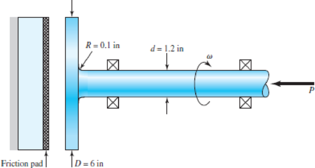
For the clutch of Prob. 6–57, the external load P is cycled between 4.5 kips and 18 kips. Assuming that the shaft is rotating synchronous with the external load cycle, estimate the number of cycles to failure. Use the modified Goodman fatigue failure criteria.
Problem 6–57
Expert Solution & Answer
Want to see the full answer?
Check out a sample textbook solution
Students have asked these similar questions
5. Design a sleeve coupling for the transmission of 12 kW at 300 rpm by two connected steel shafts. Take service factor KS 1.25. The sleeve is made of CI. The key and the shaft are made of the same material. Allowable stress: Shear stresses in key and shaft 50 MPa Crushing stress in key= 100 MPa Shear stress in CI sleeve = 10 MPa
The worm shaft shown in the figure transmits 1-kW at 500 rev/min. A static forceanalysis results are also shown in the figure. Bearing A is to be an angular-contact ballbearing mounted to take the 2.75 kN thrust load. The bearing at B is to take only theradial load, so a straight roller bearing will be employed. Use an application factor of1.2, a desired life of 25 kh, and a combined reliability goal of 0.99.
(a)Specify each bearing by giving all required charecteristics. (b) Determine the radial and thrust components of loads on each bearing. (c) Make a design assessment for each bearing and of the system.
The layout of transmission shaft carrying two pulleys B and C and supported on bearings A and D is shown in Figure below. Power is supplied to the shaft by means of a vertical belt on pulley B, that is then transmitted to pulley C carrying a horizontal belt. The maximum tension in belt on pulley B is 2.5 kN. The angle of wrap for both the pulleys is 180o and the coefficient of friction 0.24. The shaft is made of plain carbon steel 30C8 (Syt=400 N/mm2) and the factor of safety is 3. Determine the shaft diameter on strength basis.
Chapter 6 Solutions
Connect 1-semester Access Card For Shigley's Mechanical Engineering Design
Ch. 6 - A 10-mm steel drill rod was heat-treated and...Ch. 6 - Prob. 2PCh. 6 - A steel rotating-beam test specimen has an...Ch. 6 - A steel rotating-beam test specimen has an...Ch. 6 - A steel rotating-beam test specimen has an...Ch. 6 - Repeat Prob. 6-5 with the specimen having an...Ch. 6 - A steel rotating-beam test specimen has an...Ch. 6 - Derive Eq. (6-17). Rearrange the equation to solve...Ch. 6 - For the interval 103 N 106 cycles, develop an...Ch. 6 - Estimate the endurance strength of a...
Ch. 6 - Two steels are being considered for manufacture of...Ch. 6 - A 1-in-diamctcr solid round bar has a groove...Ch. 6 - A solid square rod is cantilevered at one end. The...Ch. 6 - A rectangular bar is cut from an AISI 1020...Ch. 6 - A solid round bar with diameter of 2 in has a...Ch. 6 - The rotating shaft shown in the figure is machined...Ch. 6 - The shaft shown in the figure is machined from...Ch. 6 - Solve Prob. 6-17 except with forces F1 = 1200 lbf...Ch. 6 - Bearing reactions R1 and R2 are exerted on the...Ch. 6 - A bar of steel has the minimum properties Se = 40...Ch. 6 - Repeat Prob. 6-20 but with a steady torsional...Ch. 6 - Repeat Prob. 6-20 but with a steady torsional...Ch. 6 - Repeat Prob. 6-20 but with an alternating...Ch. 6 - A bar of steel has the minimum properties Se = 40...Ch. 6 - The cold-drawn AISI KUO steel bar shown in the...Ch. 6 - Repeat Prob. 6-25 for a load that fluctuates from...Ch. 6 - An M14 2 hex-head bolt with a nut is used to...Ch. 6 - The figure shows a formed round-wire cantilever...Ch. 6 - The figure is a drawing of a 4- by 20-mm latching...Ch. 6 - The figure shows the free-body diagram of a...Ch. 6 - Solve Prob. 6-30 except let w1 = 2.5 in. w2 = l.5...Ch. 6 - For the part in Prob. 630, recommend a fillet...Ch. 6 - Prob. 33PCh. 6 - Prob. 34PCh. 6 - A part is loaded with a combination of bending,...Ch. 6 - Repeat the requirements of Prob. 6-35 with the...Ch. 6 - 6-37 to 6-46For the problem specified in the build...Ch. 6 - 6-37 to 6-46For the problem specified in the build...Ch. 6 - 637 to 646 For the problem specified in the table,...Ch. 6 - For the problem specified in the table, build upon...Ch. 6 - 6-37 to 6-46 For the problem specified in the...Ch. 6 - 6-37 to 6-46 For the problem specified in the...Ch. 6 - 6-37 to 6-46 For the problem specified in the...Ch. 6 - Problem Number Original Problem, Page Number 637...Ch. 6 - 6-37 to 6-46 For the problem specified in the...Ch. 6 - 6-37 to 6-46 For the problem specified in the...Ch. 6 - 6-47 to 6-50 For the problem specified in the...Ch. 6 - 6-47 to 6-50 For the problem specified in the...Ch. 6 - Prob. 49PCh. 6 - Prob. 50PCh. 6 - 6-51 to 6-53 For the problem specified in the...Ch. 6 - 6-51 to 6-53 For the problem specified in the...Ch. 6 - 6-51 to 6-53 For the problem specified in the...Ch. 6 - Solve Prob. 6-17 except include a steady torque of...Ch. 6 - Solve Prob. 618 except include a steady torque of...Ch. 6 - In the figure shown, shaft A, made of AISI 1020...Ch. 6 - A schematic of a clutch-testing machine is shown....Ch. 6 - For the clutch of Prob. 657, the external load P...Ch. 6 - A flat leaf spring has fluctuating stress of max =...Ch. 6 - A rotating-beam specimen with an endurance limit...Ch. 6 - A machine part will be cycled at 350 MPa for 5...Ch. 6 - The material properties of a machine part are Sut...Ch. 6 - Repeat Prob. 662 using the Goodman criterion....
Knowledge Booster


Learn more about
Need a deep-dive on the concept behind this application? Look no further. Learn more about this topic, mechanical-engineering and related others by exploring similar questions and additional content below.Similar questions
- A plate clutch has 3 discs on the driving shaft and 2 discs on the driven shaft, providing four pairs of contact surfaces. The outside diameter of the contact surfaces is 240 mm and inside diameter 120 mm. Assuming uniform pressure and coeff. Of friction is 0.3. Find the total spring load pressing the plates together to transmit 23kw power at 1475 revolution per minute. If there 6 springs each of stiffness 13 kN/m and each of the contact surfaces has worn away by 1.25 mm. find the maximum power that can be transmitted assuming uniform wear. A plate clutch has 3 discs on the driving shaft and 2 discs on the driven shaft, providing four pairs of contact surfaces. The outside diameter of the contact surfaces is 240 mm and inside diameter 120 mm. Assuming uniform pressure and coeff. Of friction is 0.3. Find the total spring load pressing the plates together to transmit 23kw power at 1475 revolution per minute. If there 6 springs each of stiffness 13 kN/m and each of the contact surfaces…arrow_forward6. Design a clamp coupling for transmitting 36 kW, at 200 rpm. Allowable shear stress in shaft is 45 MPa, allowable shear stress in key is 40 MPa, and allowable crushing stress in key is 90 MPa. The number of bolts joining the two halves is 4. The permissible tensile stress in bolts is 60 MPa. The coefficient of friction between the muff and shaft can be taken as 0.25arrow_forwardA 15 kW and 1200 r.p.m. motor drives a compressor at 300 r.p.m. through a pair of spur gears having 20° stub teeth. The centre to centre distance between the shafts is 400 mm. The motor pinion is made of forged steel having an allowable static stress as 210 MPa, while the gear is made of cast steel having allowable static stress as 140 MPa. Assuming that the drive operates 8 to 10 hours per day under light shock conditions, find from the standpoint of strength, 1. Module; 2. Face width and 3. Number of teeth and pitch circle diameter of each gear. Check the gears thus designed from the consideration of wear. The surface endurance limit may be taken as 700 MPaarrow_forward
- A 15 kW and 1200 r.p.m. motor drives a compressor at 300 r.p.m. through a pair of spur gears having 20° stub teeth. The centre to centre distance between the shafts is 400 mm. The motor pinion is made of forged steel having an allowable static stress as 210 MPa, while the gear is made of cast steel having allowable static stress as 140 MPa. Assuming that the drive operates 8 to 10 hours per day under light shock conditions, find from the standpoint of strength, 1. Module; 2. Face width and 3. Number of teeth and pitch circle diameter of each gear. Check the gears thus designed from the consideration of wear. The surface endurance limit may be taken as 700 MParrow_forwardCalculate the maximum tensile stress developed in a 1/4-20 bolt (Major dia = 0.2500" and Root dia = 0.1959"), 3" long, and a head height of 0.1875", if it is subjected to a load of 426 lbs.arrow_forwardDesign a typical rigid flange coupling for connecting a motor and a centrifugal pump shafts. The coupling needs to transmit 15 KW at 1000 rpm. The allowable shear stresses of the shaft, key and bolt materials are 60 MPa, 50 MPa and 25 MPa respectively. The shear modulus of the shaft material may be taken as 84GPa. The angle of twist of the shaft should be limited to 1 degree in 20 times the shaft diameter. Note: show complete solutionarrow_forward
- A mild steel shaft has to transmit 75 kW at 200 rpm. Design a cast Iron flange coupling for the shaft. The allowable stresses are Shear stress for the shaft and keys 40 N/mm²Shear stress for bolts = 28 N/mm²Shear stress for C.I. coupling = 20 N/mm² Take wearing stress as twice the shear stress value and number of bolts for coupling as 6.arrow_forwardA cylinder with a nominal 2.5 in ID, a 4.0 in OD, and a 3.0 in length is to be mated with a solid shaft with a nominal 2.5 in diameter. A medium drive fit is desired (as defined in Table 7-9). The cylinder and shaft are made from steel, with Sy = 100 kpsi and E = 30 Mpsi. The coefficient of friction for the steel interface is 0.7. a. Specify the maximum and minimum allowable diameters for both the cylinder hole and the shaft. b. Determine the torque that can be transmitted through this joint, assuming the shaft and cylinder are both manufactured within their tolerances such that the minimum interference is achieved. c. Suppose the shaft and cylinder are both manufactured within their tolerances such that the maximum interference is achieved. Check for yielding of the cylinder at its inner radius by finding the following: i. The pressure at the interface ii. The tangential and radial stresses in the cylinder, at its inner radius. iii. The factor of safety for static yielding of the…arrow_forward7. Design a muff coupling for joining shafts transmitting 8 kW at 400 rpm. The shaft and the key are made of steel with 45 MPa and 80 MPa allowable stresses in shear and crushing, respectively. The material of the sleeve is CI, with allowable shear stress 10 MPa. Service factor KS =1.2.arrow_forward
- A 15KW and 1200r.p.m motor drives a compressor at 300r.p.m through a pair of spur gears having 20° stub teeth .the centre to centre distance between the shafts is 400mm.the motor pinion is made to forged steel having an allowable static stress 210MPa while the gear is made of cast steel having an allowable static stress as 140MPa.Assuming that the drive operates 8 to 10 hours per day under light shock conditions,find from the standpoint of strength (a) Module;(b)face width and (c)number of teeth an pitch circle diameter of each gear.check the gears thus designed from the consideration of wear .the surface endurance limit may be taken as 700MPa.arrow_forwardA flat belt with a width of 120 mm and a thickness of 5 mm transmits power from a driving pulley with a diameter of 250 mm to a driven pulley with a diameter of 700 mm. The mass per unit length of the belt is 2.1 kg/m, and the coefficient of friction is 0.25. The input power of the belt is 60 kW at 1000 rpm. Calculate the following when the center distance is 3.5 m. (a) Maximum tensile stress of the belt(b) Axial load on each pulleyarrow_forwardDesign a typical rigid flange coupling for connecting a motor and a centrifugal pump shafts. The coupling needs to transmit 15 KW at 1000 rpm. The allowable shear stresses of the shaft, key and bolt materials are 60 MPa, 50 MPa and 25 MPa respectively. The shear modulus of the shaft material may be taken as 84GPa. The angle of twist of the shaft should be limited to 1 degree in 20 times the shaft diameter. Note: show complete handwritten solutionarrow_forward
arrow_back_ios
SEE MORE QUESTIONS
arrow_forward_ios
Recommended textbooks for you
 Elements Of ElectromagneticsMechanical EngineeringISBN:9780190698614Author:Sadiku, Matthew N. O.Publisher:Oxford University Press
 Mechanics of Materials (10th Edition)Mechanical EngineeringISBN:9780134319650Author:Russell C. HibbelerPublisher:PEARSON
 Thermodynamics: An Engineering ApproachMechanical EngineeringISBN:9781259822674Author:Yunus A. Cengel Dr., Michael A. BolesPublisher:McGraw-Hill Education
 Control Systems EngineeringMechanical EngineeringISBN:9781118170519Author:Norman S. NisePublisher:WILEY
 Mechanics of Materials (MindTap Course List)Mechanical EngineeringISBN:9781337093347Author:Barry J. Goodno, James M. GerePublisher:Cengage Learning
 Engineering Mechanics: StaticsMechanical EngineeringISBN:9781118807330Author:James L. Meriam, L. G. Kraige, J. N. BoltonPublisher:WILEY
Elements Of Electromagnetics
Mechanical Engineering
ISBN:9780190698614
Author:Sadiku, Matthew N. O.
Publisher:Oxford University Press
Mechanics of Materials (10th Edition)
Mechanical Engineering
ISBN:9780134319650
Author:Russell C. Hibbeler
Publisher:PEARSON
Thermodynamics: An Engineering Approach
Mechanical Engineering
ISBN:9781259822674
Author:Yunus A. Cengel Dr., Michael A. Boles
Publisher:McGraw-Hill Education
Control Systems Engineering
Mechanical Engineering
ISBN:9781118170519
Author:Norman S. Nise
Publisher:WILEY
Mechanics of Materials (MindTap Course List)
Mechanical Engineering
ISBN:9781337093347
Author:Barry J. Goodno, James M. Gere
Publisher:Cengage Learning
Engineering Mechanics: Statics
Mechanical Engineering
ISBN:9781118807330
Author:James L. Meriam, L. G. Kraige, J. N. Bolton
Publisher:WILEY
BEARINGS BASICS and Bearing Life for Mechanical Design in 10 Minutes!; Author: Less Boring Lectures;https://www.youtube.com/watch?v=aU4CVZo3wgk;License: Standard Youtube License