
Package: Loose Leaf For Fluid Mechanics With 1 Semester Connect Access Card
8th Edition
ISBN: 9781259638848
Author: White
Publisher: MCG
expand_more
expand_more
format_list_bulleted
Concept explainers
Videos
Textbook Question
Chapter 6, Problem 6.128P
 In the five-pipe horizontal network of Fig. P6.127, as sume that all pipes have a friction factor f = 0.025. For the given inlet and exit glow rate of 2 ft3/s of water at 20°C, determine the flow rate and direction in all pipes. If pA = 120 lbf/in2 gage, determine the pressures at points B, C, and D.
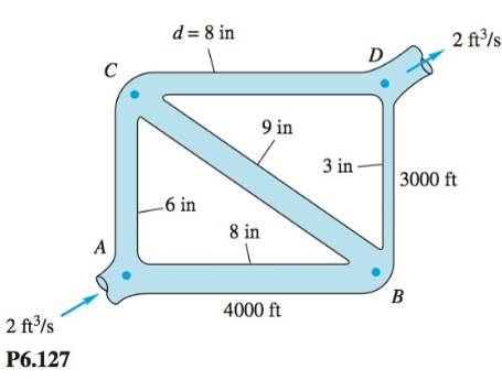
P6.128  Modify Prob. P6. 127 as follows: Let the inlet flow rate at A and the exit flow at D be unknown. Let
Expert Solution & Answer
Want to see the full answer?
Check out a sample textbook solution
Students have asked these similar questions
Two identical centrifugal pumps connected in series are used to pump water between two storage tanks that are open to the atmosphere, through a cylindrical pipe with ID of 0.1 m on both the discharge and suction side. The total equivalent length on the suction and discharge sides are 20m and 40m respectively. The change in static head is 7m.
Pump Data:
Q( m3/s)
0
0.01
0.02
0.03
0.04
Δh (m)
23
21.5
18.5
11
3
Assume the friction factor f to be 0.02 and is constant throughout the range of flowrates.
a) Determine the operating point of the system.
b) Determine the power requirement for the pumping system if the pump efficiency is 75%.
A Francis radial-flow hydroturbine has the following dimensions, where location 2 is the inlet and location 1 is the outlet: r2 = 2.00 m, r1 = 1.30 m, b2 = 0.85 m, and b1 = 2.10 m. The runner blade angles are ?2 = 71.4° and ?1 = 15.3° at the turbine inlet and outlet, respectively. The runner rotates at n. = 160 rpm. The volume flow rate at design conditions is 80.0 m3/s. Irreversible losses are neglected in this preliminary analysis. Calculate the angle ?2 through which the wicket gates should turn the flow, where ?2 is measured from the radial direction at the runner inlet. Calculate the swirl angle ?1, where ?1 is measured from the radial direction at the runner outlet. Does this turbine have forward or reverse swirl? Predict the power output (MW) and required net head (m).
Water at 16,2°C is to be discharged from a reservoir at a rate of 16,2 L/s using two horizontal cast iron (roughness value ɛ=0.00026m) pipes connected in series and a pump between them. The first pipe is 26,2 m long and has a 66,2 mm diameter, while the second pipe is 36,2 m long and has a 46,2 mm diameter. The water level in the reservoir is 30 m above the centerline of the pipe. The pipe entrance is sharp-edged (KL=0.562), and losses associated with the connection of the pump are negligible. Neglecting the effect of the kinetic energy correction factor, determine the required pumping head, the minimum pumping power and electric motor power for total efficiency value of 76,2% to maintain the indicated flow rate. Water density is r=996,2 kg/m3, dynamic viscosity µ= 1.162x10⁻³kg/ms. Solve the problem by making the necessary assumptions and drawing the schematic figure.
Chapter 6 Solutions
Package: Loose Leaf For Fluid Mechanics With 1 Semester Connect Access Card
Ch. 6 - Prob. 6.1PCh. 6 - The present pumping rate of crude oil through the...Ch. 6 - The Keystone Pipeline in the chapter opener photo...Ch. 6 - For flow of SAE 30 oil through a 5-cm-diameter...Ch. 6 - In flow past a body or wall, early transition to...Ch. 6 - P6.6 For flow of a uniform stream parallel to a...Ch. 6 - SAE 10W30 oil at 20°C flows from a tank into a...Ch. 6 - P6.8 When water at 20°C is in steady turbulent...Ch. 6 - A light liquid 950kg/m3 flows at an average...Ch. 6 - Water at 20°C flows through an inclined...
Ch. 6 - Water at 20°C flows upward at 4 m/s in a...Ch. 6 - Prob. 6.12PCh. 6 - Prob. 6.13PCh. 6 - Prob. 6.14PCh. 6 - Prob. 6.15PCh. 6 - Prob. 6.16PCh. 6 - P6.17 A capillary viscometer measures the time...Ch. 6 - P6.18 SAE 50W oil at 20°C flows from one tank to...Ch. 6 - Prob. 6.19PCh. 6 - The oil tanks in Tinyland are only 160 cm high,...Ch. 6 - Prob. 6.21PCh. 6 - Prob. 6.22PCh. 6 - Prob. 6.23PCh. 6 - Prob. 6.24PCh. 6 - Prob. 6.25PCh. 6 - Prob. 6.26PCh. 6 - Let us attack Prob. P6.25 in symbolic fashion,...Ch. 6 - Prob. 6.28PCh. 6 - Prob. 6.29PCh. 6 - Prob. 6.30PCh. 6 - A laminar flow element (LFE) (Meriam Instrument...Ch. 6 - SAE 30 oil at 20°C flows in the 3-cm.diametcr pipe...Ch. 6 - Prob. 6.33PCh. 6 - Prob. 6.34PCh. 6 - In the overlap layer of Fig. 6.9a, turbulent shear...Ch. 6 - Prob. 6.36PCh. 6 - Prob. 6.37PCh. 6 - Prob. 6.38PCh. 6 - Prob. 6.39PCh. 6 - Prob. 6.40PCh. 6 - P6.41 Two reservoirs, which differ in surface...Ch. 6 - Prob. 6.42PCh. 6 - Prob. 6.43PCh. 6 - P6.44 Mercury at 20°C flows through 4 m of...Ch. 6 - P6.45 Oil, SG = 0.88 and v = 4 E-5 m2/s, flows at...Ch. 6 - Prob. 6.46PCh. 6 - Prob. 6.47PCh. 6 - Prob. 6.48PCh. 6 - Prob. 6.49PCh. 6 - Prob. 6.50PCh. 6 - Prob. 6.51PCh. 6 - Prob. 6.52PCh. 6 - Water at 2OC flows by gravity through a smooth...Ch. 6 - A swimming pool W by Y by h deep is to be emptied...Ch. 6 - Prob. 6.55PCh. 6 - Prob. 6.56PCh. 6 - Prob. 6.57PCh. 6 - Prob. 6.58PCh. 6 - P6.59 The following data were obtained for flow of...Ch. 6 - Prob. 6.60PCh. 6 - Prob. 6.61PCh. 6 - Water at 20°C is to be pumped through 2000 ft of...Ch. 6 - Prob. 6.63PCh. 6 - Prob. 6.64PCh. 6 - Prob. 6.65PCh. 6 - Prob. 6.66PCh. 6 - Prob. 6.67PCh. 6 - Prob. 6.68PCh. 6 - P6.69 For Prob. P6.62 suppose the only pump...Ch. 6 - Prob. 6.70PCh. 6 - Prob. 6.71PCh. 6 - Prob. 6.72PCh. 6 - Prob. 6.73PCh. 6 - Prob. 6.74PCh. 6 - Prob. 6.75PCh. 6 - P6.76 The small turbine in Fig. P6.76 extracts 400...Ch. 6 - Prob. 6.77PCh. 6 - Prob. 6.78PCh. 6 - Prob. 6.79PCh. 6 - The head-versus-flow-rate characteristics of a...Ch. 6 - Prob. 6.81PCh. 6 - Prob. 6.82PCh. 6 - Prob. 6.83PCh. 6 - Prob. 6.84PCh. 6 - Prob. 6.85PCh. 6 - SAE 10 oil at 20°C flows at an average velocity of...Ch. 6 - A commercial steel annulus 40 ft long, with a = 1...Ch. 6 - Prob. 6.88PCh. 6 - Prob. 6.89PCh. 6 - Prob. 6.90PCh. 6 - Prob. 6.91PCh. 6 - Prob. 6.92PCh. 6 - Prob. 6.93PCh. 6 - Prob. 6.94PCh. 6 - Prob. 6.95PCh. 6 - Prob. 6.96PCh. 6 - Prob. 6.97PCh. 6 - Prob. 6.98PCh. 6 - Prob. 6.99PCh. 6 - Prob. 6.100PCh. 6 - Prob. 6.101PCh. 6 - *P6.102 A 70 percent efficient pump delivers water...Ch. 6 - Prob. 6.103PCh. 6 - Prob. 6.104PCh. 6 - Prob. 6.105PCh. 6 - Prob. 6.106PCh. 6 - Prob. 6.107PCh. 6 - P6.108 The water pump in Fig. P6.108 maintains a...Ch. 6 - In Fig. P6.109 there are 125 ft of 2-in pipe, 75...Ch. 6 - In Fig. P6.110 the pipe entrance is sharp-edged....Ch. 6 - For the parallel-pipe system of Fig. P6.111, each...Ch. 6 - Prob. 6.112PCh. 6 - Prob. 6.113PCh. 6 - Prob. 6.114PCh. 6 - Prob. 6.115PCh. 6 - Prob. 6.116PCh. 6 - Prob. 6.117PCh. 6 - Prob. 6.118PCh. 6 - Prob. 6.119PCh. 6 - Prob. 6.120PCh. 6 - Prob. 6.121PCh. 6 - Prob. 6.122PCh. 6 - Prob. 6.123PCh. 6 - Prob. 6.124PCh. 6 - Prob. 6.125PCh. 6 - Prob. 6.126PCh. 6 - Prob. 6.127PCh. 6 - In the five-pipe horizontal network of Fig....Ch. 6 - Prob. 6.129PCh. 6 - Prob. 6.130PCh. 6 - Prob. 6.131PCh. 6 - Prob. 6.132PCh. 6 - Prob. 6.133PCh. 6 - Prob. 6.134PCh. 6 - An airplane uses a pitot-static tube as a...Ch. 6 - Prob. 6.136PCh. 6 - Prob. 6.137PCh. 6 - Prob. 6.138PCh. 6 - P6.139 Professor Walter Tunnel needs to measure...Ch. 6 - Prob. 6.140PCh. 6 - Prob. 6.141PCh. 6 - Prob. 6.142PCh. 6 - Prob. 6.143PCh. 6 - Prob. 6.144PCh. 6 - Prob. 6.145PCh. 6 - Prob. 6.146PCh. 6 - Prob. 6.147PCh. 6 - Prob. 6.148PCh. 6 - Prob. 6.149PCh. 6 - Prob. 6.150PCh. 6 - Prob. 6.151PCh. 6 - Prob. 6.152PCh. 6 - Prob. 6.153PCh. 6 - Prob. 6.154PCh. 6 - Prob. 6.155PCh. 6 - Prob. 6.156PCh. 6 - Prob. 6.157PCh. 6 - Prob. 6.158PCh. 6 - Prob. 6.159PCh. 6 - Prob. 6.160PCh. 6 - Prob. 6.161PCh. 6 - Prob. 6.162PCh. 6 - Prob. 6.163PCh. 6 - Prob. 6.1WPCh. 6 - Prob. 6.2WPCh. 6 - Prob. 6.3WPCh. 6 - Prob. 6.4WPCh. 6 - Prob. 6.1FEEPCh. 6 - Prob. 6.2FEEPCh. 6 - Prob. 6.3FEEPCh. 6 - Prob. 6.4FEEPCh. 6 - Prob. 6.5FEEPCh. 6 - Prob. 6.6FEEPCh. 6 - Prob. 6.7FEEPCh. 6 - Prob. 6.8FEEPCh. 6 - Prob. 6.9FEEPCh. 6 - Prob. 6.10FEEPCh. 6 - Prob. 6.11FEEPCh. 6 - Prob. 6.12FEEPCh. 6 - Prob. 6.13FEEPCh. 6 - Prob. 6.14FEEPCh. 6 - Prob. 6.15FEEPCh. 6 - Prob. 6.1CPCh. 6 - Prob. 6.2CPCh. 6 - Prob. 6.3CPCh. 6 - Prob. 6.4CPCh. 6 - Prob. 6.5CPCh. 6 - Prob. 6.6CPCh. 6 - Prob. 6.7CPCh. 6 - Prob. 6.8CPCh. 6 - Prob. 6.9CPCh. 6 - A hydroponic garden uses the 10-m-long...Ch. 6 - It is desired to design a pump-piping system to...
Knowledge Booster


Learn more about
Need a deep-dive on the concept behind this application? Look no further. Learn more about this topic, mechanical-engineering and related others by exploring similar questions and additional content below.Similar questions
- 4. Air flows isentropically through the channel To = 300 ° C. both ends have an identical area that is A = 25 cm², pressure p1 = 120 kPa and p2 = 60 kPa. Determine : a). Mass flow rate, b). Throat area C). Ma2arrow_forwardA fan draws 2.42 m^3 per second of air at a static pressure of 2.54 cm water through a duct 300 mm diameter and discharges it through a duct of 275 mm diameter. Determine the static fan efficiency IN PERCENT if total fan mechanical is 75 percent and air is measured at 25 deg. Celsius and 760 mm Hg.arrow_forwardA Francis radial-flow hydroturbine is being designed with the following dimensions: r2 = 2.00 m, r1 = 1.42 m, b2 = 0.731 m, and b1 = 2.20 m. The runner rotates at n. = 180 rpm. The wicket gates turn the flow by angle ?2 = 30° from radial at the runner inlet, and the flow at the runner outlet is at angle ?1 = 10° from radial. The volume flow rate at design conditions is 340 m3 /s, and the gross head provided by the dam is Hgross = 90.0 m. For the preliminary design, irreversible losses are neglected. Calculate the turbine specific speed of the turbine. Provide answers in both dimensionless form and in customary U.S. units. Is it in the normal range for a Francis turbine? If not, what type of turbine would be more appropriate?arrow_forward
- A Francis radial-flow hydroturbine is being designed with the following dimensions: r2 = 2.00 m, r1 = 1.42 m, b2 = 0.731 m, and b1 = 2.20 m. The runner rotates at n. = 180 rpm. The wicket gates turn the flow by angle ?2 = 30° from radial at the runner inlet, and the flow at the runner outlet is at angle ?1 = 10° from radial. The volume flow rate at design conditions is 340 m3 /s, and the gross head provided by the dam is Hgross = 90.0 m. For the preliminary design, irreversible losses are neglected. Calculate the inlet and outlet runner blade angles ?2 and ?1, respectively, and predict the power output (MW) and required net head (m). Is the design feasible?arrow_forwardA 60-cm water pipe carries a flow of 0.1 m³/s. At point A the elevation is 50 meters and the pressure is 200 kPa. At point B, 1200 meters downstream from A, the elevation is 40 meters and the pressure is 230 kPa. The head loss , in feet, between A and B isA. 6.94B. 15.0C. 20.88D. 100.2arrow_forwardWater fl owing in a smooth 6-cm-diameter pipe entersa venturi contraction with a throat diameter of 3 cm.Upstream pressure is 120 kPa. If cavitation occurs in thethroat at a fl ow rate of 155 gal/min, what is the estimatedfl uid vapor pressure, assuming ideal frictionless fl ow?( a ) 6 kPa, ( b ) 12 kPa, ( c ) 24 kPa, ( d ) 31 kPa, ( e ) 52 kPaarrow_forward
- A fully-filled open storage tower of height 32 m and diameter 3.0m supplies water to a house. A horizontal pipe at the base of the tower has a diameter of 2.54cm. To satisfy the needs of the home, the supply pipe must be able to deliver water at a rate of 0.67 gal/s. a. If water were flowing at the maximum rate, what would be the pressure in the horizontal pipe?b. A smaller pipe, of diameter 1.27 cm supplies the second floor of the house, a distance of 7.2 m above the ground level. What are the flow speed and water pressure in this pipe?arrow_forwardPaolo owns a hydroelectric power generating system as shown in HG008. Water flows from an upper reservoir to a lower one passing through a turbine at the rate of 150 lps. The total length of pipe connecting the two reservoir is 100 m. The pipe diameter is 250 mm and the Hazen – Williams coefficient is 120. The water surface elevations of reservoirs 1 and 2 are 197 m and 50 m, respectively. Find the velocity of flow in pipe in m/s.arrow_forwarda fan draws 1.42m3 per second of air at a static pressure of 2.54 cm of water through a duct 300 mm diameter and discharges it through a duct of 275 mm diameter. Determine the static fan efficiency if total fan is 75% and air is measured at 25 degree celsius and 760 mm Hgarrow_forward
- A backward-swept centrifugal fan develops a pressure of 80 mm of water gauge. It has an impeller diameter of 0.89 m and runs at 720 rpm. The blade angle at the tip is 39° and the width of the impeller is 0.1m. Assuming a constant radial velocity of 9.15 m/s and density of air as 1.2 kg/ m3 , determine the fan efficiency, discharge and power required.arrow_forwardMinor losses through valves, fi ttings, bends, contractions,and the like are commonly modeled as proportional to(a) total head, (b) static head, (c) velocity head, (d) pressuredrop, (e) velocityarrow_forwardSuppose the pump of Fig. P14–23 is operating atfree delivery conditions. The pipe, both upstream and downstreamof the pump, has an inner diameter of 2.0 cm andnearly zero roughness. The minor loss coefficient associatedwith the sharp inlet is 0.50, each valve has a minor loss coefficientof 2.4, and each of the three elbows has a minor losscoefficient of 0.90. The contraction at the exit reduces thediameter by a factor of 0.60 (60% of the pipe diameter), andthe minor loss coefficient of the contraction is 0.15. Note thatthis minor loss coefficient is based on the average exit velocity,not the average velocity through the pipe itself. The total length of pipe is 6.7 m, and the elevation difference is (z1 - z2)= 4.6 m. Estimate the volume flow rate through this pipingsystem. Complete Answer, Thank youarrow_forward
arrow_back_ios
SEE MORE QUESTIONS
arrow_forward_ios
Recommended textbooks for you
 Elements Of ElectromagneticsMechanical EngineeringISBN:9780190698614Author:Sadiku, Matthew N. O.Publisher:Oxford University Press
 Mechanics of Materials (10th Edition)Mechanical EngineeringISBN:9780134319650Author:Russell C. HibbelerPublisher:PEARSON
 Thermodynamics: An Engineering ApproachMechanical EngineeringISBN:9781259822674Author:Yunus A. Cengel Dr., Michael A. BolesPublisher:McGraw-Hill Education
 Control Systems EngineeringMechanical EngineeringISBN:9781118170519Author:Norman S. NisePublisher:WILEY
 Mechanics of Materials (MindTap Course List)Mechanical EngineeringISBN:9781337093347Author:Barry J. Goodno, James M. GerePublisher:Cengage Learning
 Engineering Mechanics: StaticsMechanical EngineeringISBN:9781118807330Author:James L. Meriam, L. G. Kraige, J. N. BoltonPublisher:WILEY
Elements Of Electromagnetics
Mechanical Engineering
ISBN:9780190698614
Author:Sadiku, Matthew N. O.
Publisher:Oxford University Press
Mechanics of Materials (10th Edition)
Mechanical Engineering
ISBN:9780134319650
Author:Russell C. Hibbeler
Publisher:PEARSON
Thermodynamics: An Engineering Approach
Mechanical Engineering
ISBN:9781259822674
Author:Yunus A. Cengel Dr., Michael A. Boles
Publisher:McGraw-Hill Education
Control Systems Engineering
Mechanical Engineering
ISBN:9781118170519
Author:Norman S. Nise
Publisher:WILEY
Mechanics of Materials (MindTap Course List)
Mechanical Engineering
ISBN:9781337093347
Author:Barry J. Goodno, James M. Gere
Publisher:Cengage Learning
Engineering Mechanics: Statics
Mechanical Engineering
ISBN:9781118807330
Author:James L. Meriam, L. G. Kraige, J. N. Bolton
Publisher:WILEY
Fluid Mechanics - Viscosity and Shear Strain Rate in 9 Minutes!; Author: Less Boring Lectures;https://www.youtube.com/watch?v=_0aaRDAdPTY;License: Standard youtube license