
Concept explainers
Videos
Carefully sketch the energy grade lines (EGL) and hydraulic grade lines (HGL) for the system shown in Fig. 6.6 if the pipe is horizontal (i.e., the outlet is at the base of the reservoir), and a water turbine (extracting energy) is located at point ②, or at point ③. In Chapter 8 we will investigate the effects of friction on internal flows. Can you anticipate and sketch the effect of friction on the EGL and HGL for the two cases?
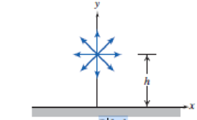
P6.6
Want to see the full answer?
Check out a sample textbook solution
Chapter 6 Solutions
Fox and McDonald's Introduction to Fluid Mechanics
Additional Engineering Textbook Solutions
Automotive Technology: Principles, Diagnosis, And Service (6th Edition) (halderman Automotive Series)
Fundamentals of Heat and Mass Transfer
Applied Statics and Strength of Materials (6th Edition)
Thinking Like an Engineer: An Active Learning Approach (3rd Edition)
DeGarmo's Materials and Processes in Manufacturing
Mechanics of Materials (10th Edition)


- CalculatorWater flows through a horizontal duct of diameter 0.5 m with a velocity of 0.4 m/s. If the friction factor is 0.002 calculate the pressure difference between two points 24.8 m apart. Assume the density of water is 1000 kg/m3 Your answer should be in Pascalsarrow_forward9.7. Through a hydraulic turbine flow 2.8 m3/s of water. On the 1 m inlet pipe at elevation 43.5,a pressure gage reads 345 kPa. On the 1.5 m discharge pipe at elevation 39, a vacuum gage reads150 mm of mercury. If the total head lost through pipes and turbines between elevations 43.5and 39 is 9 m, what power may be expected from the machine?arrow_forwardA vessel is being filled with water through an inlet at section 1 having a diameter of 40 mm and a faucet at section 3. The velocity at section 1 is given as 5 m/s, while the discharge at section 3 is given as 0.012 m^3/ s. Assume constant water level. Use 60 mm for the diameter of the outlet at section 2. A. What is the discharge at section 2? B. What is exit velocity at section 2? C. If the water level varies and the velocity at section 2 is 8m/s find the rate of change when d is equal to 1000mm?arrow_forward
- Homework Question: The pipe bend as in the figure below has D1 = 29 cm and D2 = 12 cm. When water at 20°C flows through the pipe at 4000 gal/ min, p1 = 215 kPa (gage). Compute the torque (magnitude and direction) required at point B to hold the bend stationary? HINT : D1 = 29 cm and D2 = 12 cm & p1 = 215 kPa (gage).arrow_forwardFor the pipe system shown. Assume n = 0.013 for all pipes. Neglect minor losses. 1. Compute the head loss from A to B in terms of Q. a. 0.056Q2 b. 0.029Q2 c. 0.016Q2 d. 0.096Q2 2. Assuming Q = 12 cfs, compute the head loss of pipe CD. a. 15.78 ft b. 13.02 ft c. 18.56 ft d. 24.56 ft 3. Assuming Q = 12 cfs, compute the total head loss from A to D. a. 47.786 ft b. 56.673 ft c. 89.451 ft d. 32.562 ftarrow_forwardUsing affinity laws, develop a pump curve and BHP curve for a 1 ½" AB pump for a 6" impeller. Use a 1750 rpm curve as the "known" characteristics and develop a theoretical curve using affinity laws for 3500 rpm based upon flow rates 0, 20, 40, 60, 80 and 90 gpm at 1750 rpm. Plot the theoretical (affinity-based) and published flow vs. head and flow vs. horsepower curves for 3500 rpm.arrow_forward
- 4. Brine (SG = 1.1, viscosity = 1.1cP) is pumped at a rate of 45 ft^3/min (ID = 2.5in) from large open reservoir to the bottom of another open tank. The liquid level in the reservoir is maintained at 5.2ft, and the liquid level in the reservoir and the bottom of the discharge tank are 18ft apart, vertically. Friction losses in the pipe amount to 10% of the elevation head. If 2.15 hp of power is required for the process, what is the expected liquid level in the receiving tank?arrow_forwardThe below figure shows a pump that transfers a steady stream of 35◦API crude oil from an oiltanker to a refinery storage tank, both free surfaces being open to the atmosphere. Theeffective length—including fittings—of the commercial steel pipe is 6,000 ft. The dischargeat point 4 is 200 ft above the pump exit, which is level with the free surface of oil in thetanker. However, because of an intervening hill, point 3 is at a higher altitude than point 4.Losses between points 1 and 2 may be ignored.The crude oil has the following properties:Density ρ = 53 lbm/ft 3 ; Viscosity μ = 13.2 cP; Vapour Pressure Pv = 4.0 psia Answer the following questions:1. If the combination of pump and motor is 80% efficient, how much electrical power(kW) is needed to drive the pump?2. If, in order to avoid vapour lock, the pressure in the pipeline must always be above thevapor pressure of the crude oil, what is the maximum permissible elevation of point 3relative to point 4?3. If the flow in the pipeline…arrow_forwardThe plunger diameter of a single-acting reciprocating pump is 115 mm and the stroke is 230 mm. The suction pipe is 90 mm in diameter and 4.2 m long. If cavitation takes place at the suction head of 4 m, the barometer stands at 10.3 m of water, and the water level in the sump is 3 m below the pump cylinder axis.3.1 Find the maximum allowable speed to operate the pump3.2 What power is expected in overcoming friction at this speed, take ƒ = 0.01arrow_forward
- Explain the basic working principles, main parameters, performance, efficiency, etc., of pumps in your words minimum 200 words, Result Analysis, Discussion & Conclusions From your results, describe the link between flow rate with efficiency, head and power. Discuss the point where the pump is most efficient? https://www.youtube.com/watch?v=Pj7qs2-dvVwarrow_forwardA horizontal 300-mm pipe contracts to a 150-mm diameter. If the flow is 0.127 m3/s of oil (s.g.=0.88) and the pressure in the smaller pipe is 265 kPa what force is exerted on the contraction, neglecting friction?arrow_forwardPROBLEM 1: Water flows upwards in a vertical pipeline of gradually varying section from point 1 to point 2, which is 1.5m above point 1, at the rate of 0.9m^3/s. At section 1 the pipe diameter is 0.5m and pressure is 800 kPa. If pressure at section 2 is 600 kPa, determine the pipe diameter at that location. Neglect losses.arrow_forward
 Elements Of ElectromagneticsMechanical EngineeringISBN:9780190698614Author:Sadiku, Matthew N. O.Publisher:Oxford University Press
 Mechanics of Materials (10th Edition)Mechanical EngineeringISBN:9780134319650Author:Russell C. HibbelerPublisher:PEARSON
 Thermodynamics: An Engineering ApproachMechanical EngineeringISBN:9781259822674Author:Yunus A. Cengel Dr., Michael A. BolesPublisher:McGraw-Hill Education
 Control Systems EngineeringMechanical EngineeringISBN:9781118170519Author:Norman S. NisePublisher:WILEY
 Mechanics of Materials (MindTap Course List)Mechanical EngineeringISBN:9781337093347Author:Barry J. Goodno, James M. GerePublisher:Cengage Learning
 Engineering Mechanics: StaticsMechanical EngineeringISBN:9781118807330Author:James L. Meriam, L. G. Kraige, J. N. BoltonPublisher:WILEY