
Control Systems Engineering
7th Edition
ISBN: 9781118170519
Author: Norman S. Nise
Publisher: WILEY
expand_more
expand_more
format_list_bulleted
Concept explainers
Videos
Textbook Question
Chapter 6, Problem 6P
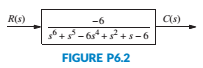
Determine how many closed-loop poles lie in the right half-plane. In the left half-plane, and on the
6. How many poles are in the tight half-plane, in the left half-plane, and on the
Expert Solution & Answer
Want to see the full answer?
Check out a sample textbook solution
Students have asked these similar questions
Given the system equipped with unitary feedback, whose direct branch transfer function is:
Design a PID controller with one of the Ziegler-Nichols methods.
A vibrating spring-mass system has the feedback control system shown in Fig Q3 below. (figure attached as image ACT)If K = 12.25 determine:6.1 the transfer function ; (3)6.2 the characteristic equation with a impulse input; (1)6.3 the un-damped natural frequency of the system; (2)6.4 the damping ratio; (2)6.5 the damped natural frequency; (2)6.6 the maximum percentage overshoot; (2)6.7 the peak time; (1)6.8 the settling time for the response within 2%. (2)
1. Give an example of open loop and closed loop system (one example each). Also state the input, control system, feedback and output parameter.
Example.
1. Open Loop - Water Heater:
Input - Water Temperature (Cold)
System - Heating Element
Output - Water Temperature (Hot)
2. Closed Loop - Air-conditioning System
Input - Desired Room Temperature
Control - Motor controller/Compressor/ACU
Feedback - Temperature Sensing
Output - Room Temperature
Chapter 6 Solutions
Control Systems Engineering
Ch. 6 - Prob. 1RQCh. 6 - Prob. 2RQCh. 6 - What would happen to a physical system chat...Ch. 6 - Why are marginally stable systems considered...Ch. 6 - Prob. 5RQCh. 6 - Prob. 6RQCh. 6 - Prob. 7RQCh. 6 - Prob. 8RQCh. 6 - Prob. 9RQCh. 6 - Why do we sometimes multiply a row of a Routh...
Ch. 6 - Prob. 11RQCh. 6 - Prob. 12RQCh. 6 - 13. Does the presence of an entire row of zeros...Ch. 6 - Prob. 14RQCh. 6 - Prob. 15RQCh. 6 - Prob. 16RQCh. 6 - Tell how many roots of the following polynomial...Ch. 6 - Tell how many roots of the following polynomial...Ch. 6 - Using the Routh table, tell how many poles of the...Ch. 6 - Prob. 4PCh. 6 - Determine how many closed-loop poles lie in the...Ch. 6 - Determine how many closed-loop poles lie in the...Ch. 6 - MATLAB ML 7. Use MATLAB to find the pole location...Ch. 6 - Symbolic Math SM 8. Use MATLAB and the Symbolic...Ch. 6 - Determine whether the unity feedback system of...Ch. 6 - Use MATLAB to find the pole locations for the...Ch. 6 - Consider the unity feedback system of Figure P6.3...Ch. 6 - In the system of Figure P6.3, let Gs=Ks+1ss2s+3...Ch. 6 - Given the unity feedback system of Figure P6.3...Ch. 6 - Using the Routh-Hurwitz criterion and the unity...Ch. 6 - Given the unity feedback system of Figure P6.3...Ch. 6 - Repeat Problem 15 using MATLAB.Ch. 6 - Prob. 17PCh. 6 - For the system of Figure P6.4, tell how many...Ch. 6 - Using the Routh-Hurwitz criterion, tell how many...Ch. 6 - Determine if the unity feedback system of Figure...Ch. 6 - For the unity feedback system of Figure P6.3 with...Ch. 6 - In the system of Figure P6.3, let Gs=Ksassb Find...Ch. 6 - For the unity feedback system of Figure P63 with...Ch. 6 - Find the range of K for stability for the unity...Ch. 6 - For the unity feedback system of Figure P6.3 with...Ch. 6 - find the range of K for stability. [Section: 6.41]...Ch. 6 - Find the range of gain, K, to ensure stability in...Ch. 6 - Using the Routh-Hurwitz criterion, find the value...Ch. 6 - Use the Routh-Hurwitz criterion to find the range...Ch. 6 - Prob. 32PCh. 6 - Given the unity feedback system of Figure P63 with...Ch. 6 - Repeat Problem 33 for [Section: 6.4]...Ch. 6 - For the system shown in Figure P6.8, find the...Ch. 6 - Given the unity feedback system of Figure P6.3...Ch. 6 - For the unity feedback system of Figure P6.3 with...Ch. 6 - For the unity feedback system of Figure P6.3 with...Ch. 6 - Given the unity feedback system of Figure P6.3...Ch. 6 - Using the Routh-Hurwitz criterion and the unity...Ch. 6 - Find the range of K to keep the system shown in...Ch. 6 - Prob. 43PCh. 6 - The closed-loop transfer function of a system is...Ch. 6 - Prob. 45PCh. 6 - Prob. 46PCh. 6 - An interval polynomial is of the form...Ch. 6 - A linearized model of a torque-controlled crane...Ch. 6 - The read/write head assembly arm of a computer...Ch. 6 - A system is represented in state space as...Ch. 6 - State Space SS 52. The following system in state...Ch. 6 - Prob. 54PCh. 6 - A model for an airplane’s pitch loop is shown in...Ch. 6 - Prob. 57PCh. 6 - Prob. 58PCh. 6 - Prob. 59PCh. 6 - Prob. 60PCh. 6 - Prob. 61PCh. 6 - Look-ahead information can be used to...Ch. 6 - Prob. 63PCh. 6 - It has been shown (Pounds, 2011) that an unloaded...Ch. 6 - Prob. 65PCh. 6 - The system shown in Figure P6.16 has G1s=1/ss+2s+4...Ch. 6 - Prob. 67PCh. 6 - Prob. 68PCh. 6 - Hybrid vehicle. Figure P6.l8 shows the HEV system...Ch. 6 - Prob. 70P
Knowledge Booster


Learn more about
Need a deep-dive on the concept behind this application? Look no further. Learn more about this topic, mechanical-engineering and related others by exploring similar questions and additional content below.Similar questions
- A Block diagram of a feedback control system is shown in Figure Q3. Using the Block Diagram Reduction Method, solve for the output Y(s) when:(i) Input D(s) = 0,(ii) Input R(s) = 0,(iii) Input R(s) and D(s) are both applied (i.e., R(s) ≠ 0 , D(s) ≠ 0).arrow_forwardTIME DOMAIN MODELING AND RESPONSE FOR CONTROL SYSTEMSarrow_forward(Figure 1 One Wheel Model), Part1-(Derive equation of motion for a given system and obtain transfer function and state space representation.) , part2-(Draw closed-loop diagram for full-state- feedback controller.) , part3- (Select proper coefficient (u=-Kx) satisfying that .) part4- (Simulate the closed-loop system and show the response of it.) Note: Tahe Reference signal as With f = 0.1 Hz. !!!!!!!!! Please solve these steps, at least the first step which is writing the equations of motion of the system and the second step which is drawing closed loop diagram for Full state feedback controller.!!!!arrow_forward
- Reduce the block diagram shown in Figure below to a single transfer function, T(s) = C(s)/R(s) Use the block diagram reduction method.arrow_forwardQ.1 - The open loop transfer function for a unity - feedback systemis G(s)= XL‘ 7xs and r(t)=3t determine steady state error.If it is desired to reduce this existing error by 7% fined new value of gain of the system.arrow_forwardA stock-flow system models the level of water in a lake. Near a certain equilibrium point, there are three feedback loops: an amplifying feedback loop with strength of +0.55 per month, a stabilizing feedback loop with strength of -0.09 per month, and an amplifying feedback loop with strength of +0.79 per month. Calculate the strength of the overall feedback.arrow_forward
- explain please. Which type(s) of systems will oscillate in response to a step function?arrow_forwarda)is the aircraft stable about the equilibrium represented by the transfer function? b) Using proportional feedback,what is the range of acceptable gains for the closed loop systen to be stable? c) Design a feedback control system that allows the pilot to command a pitch angle with overshoot less than or equal to 4.15% and a natural frequency of greater than or equal to 0.99 rad/s d) Design a feedback control system that allows the pilot to command a pitch angle with the same overshoot and a natural frequency of one half the system in part c.arrow_forwardroot locus electrical engineering Don't overthink and reject. Complete the solution as per the given transfer function. No need of quadratic equation just simplify for the exact given transfer function.arrow_forward
- Sketch the level response for a bathtub with cross-sectional area of 8 ft 2 as a function of time for the following sequence of events; assume an initial level of 0.5 ft with the drain open. The inflow and outflow are initially equal to2ft3/min.(a)The drain is suddenly closed, and the inflow remains con-stant for 3 min (0≤t≤3).(b)The drain is opened for 15 min; assume a time constant in a linear transfer function of 3 min, so a steady state is essentially reached (3≤t≤18) (c)The inflow rate is doubled for 6 min (18≤t≤24).(d)The inflow rate is returned to its original value for 16 min(24≤t≤40).arrow_forward1.block diagram physical meaning and the time response for different inputsarrow_forward(system dynamics and control) q2 is given in image q3) ?arrow_forward
arrow_back_ios
SEE MORE QUESTIONS
arrow_forward_ios
Recommended textbooks for you
 Elements Of ElectromagneticsMechanical EngineeringISBN:9780190698614Author:Sadiku, Matthew N. O.Publisher:Oxford University Press
 Mechanics of Materials (10th Edition)Mechanical EngineeringISBN:9780134319650Author:Russell C. HibbelerPublisher:PEARSON
 Thermodynamics: An Engineering ApproachMechanical EngineeringISBN:9781259822674Author:Yunus A. Cengel Dr., Michael A. BolesPublisher:McGraw-Hill Education
 Control Systems EngineeringMechanical EngineeringISBN:9781118170519Author:Norman S. NisePublisher:WILEY
 Mechanics of Materials (MindTap Course List)Mechanical EngineeringISBN:9781337093347Author:Barry J. Goodno, James M. GerePublisher:Cengage Learning
 Engineering Mechanics: StaticsMechanical EngineeringISBN:9781118807330Author:James L. Meriam, L. G. Kraige, J. N. BoltonPublisher:WILEY
Elements Of Electromagnetics
Mechanical Engineering
ISBN:9780190698614
Author:Sadiku, Matthew N. O.
Publisher:Oxford University Press
Mechanics of Materials (10th Edition)
Mechanical Engineering
ISBN:9780134319650
Author:Russell C. Hibbeler
Publisher:PEARSON
Thermodynamics: An Engineering Approach
Mechanical Engineering
ISBN:9781259822674
Author:Yunus A. Cengel Dr., Michael A. Boles
Publisher:McGraw-Hill Education
Control Systems Engineering
Mechanical Engineering
ISBN:9781118170519
Author:Norman S. Nise
Publisher:WILEY
Mechanics of Materials (MindTap Course List)
Mechanical Engineering
ISBN:9781337093347
Author:Barry J. Goodno, James M. Gere
Publisher:Cengage Learning
Engineering Mechanics: Statics
Mechanical Engineering
ISBN:9781118807330
Author:James L. Meriam, L. G. Kraige, J. N. Bolton
Publisher:WILEY
Introduction to Undamped Free Vibration of SDOF (1/2) - Structural Dynamics; Author: structurefree;https://www.youtube.com/watch?v=BkgzEdDlU78;License: Standard Youtube License