
Concept explainers
Videos
(a)
Show that the magnitude of the horizontal shearing force H exerted on the lower face of the portion of the beam ACKJ is
(a)
Answer to Problem 60P
The magnitude of the horizontal shearing force H exerted on the lower face of the portion of the beam ACKJ is
Explanation of Solution
Given information:
K is a point at a distance
Calculation:
The point K is located a distance y above the neutral axis.
Provide the stress distribution as shown below.
Sketch the stress distribution for
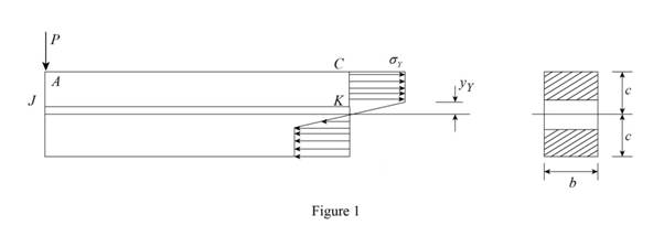
Sketch the stress distribution for
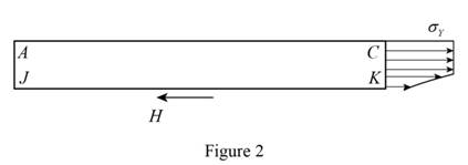
Calculate the horizontal forces acting on ACKJ as shown below.
Substitute
Therefore, the magnitude of the horizontal shearing force H exerted on the lower face of the portion of the beam ACKJ is
(b)
The shearing stress at K.
(b)
Answer to Problem 60P
The shearing stress at K is
Explanation of Solution
Given information:
K is a point at a distance
Calculation:
Refer to part (a).
The horizontal shearing force is
Calculate the shear stress as shown below.
Substitute
Provide the relation of moment as shown below.
Differentiate both sides of the Equation as shown below.
Substitute
Substitute
Therefore, the shearing stress at K is
Want to see more full solutions like this?
Chapter 6 Solutions
Connect 1-semester Access Card For Mechanics Of Materials - 2016 Update


- A 12-m simply supported overhang beam is supported at x = 0 and x = 10m. The overhanging portion is from x = 10m to x = 12m (the overhang portion is 2m). Two equal wheel loads of 20kN each, separated by 2m roll as a unit across the 12-m span. Determine the maximum shear developed in the span.arrow_forwardFive metal strips, each of 0.5 * 1.5-in. cross section, are bonded together to form the composite beam shown. The modulus of elasticity is 30* 106 psi for the steel, 15 *106 psi for the brass, 10 *106 psi for the aluminum. Knowing that the beam is bent about a horizontal axis by a couple of moment 12 kip·in., determine (a) the maximum stress in each of the three metals, (b) the radius of curvature of the composite beam.arrow_forwardSolve Prob. 7.89 assuming that the bending moment was found to be +650 N.m at D and +1450 N.m at E.(Reference to Problem 7.89):The beam AB is subjected to the uniformly distributed load shown and to two unknown forces P and Q . Knowing that it has been experimentally determined that the bending moment is +800 N.m at D and +1300 at E, (a) determine P and Q,(b) draw the shear and bending-moment diagrams for the beam.arrow_forward
- Suppose that w1 = 15 kN/m and w2 = 7.5 kN/m. Specify the location of FR on the beam, measured from point B to the right.arrow_forwardA) The four cross sections shown have different characteristics when subjected to a vertical shear force. Which of the four geometries shown has the largest value for the moment of the area, Q, about the neutral axis? B) Which of the four geometries shown has the smallest value for its moment of inertia about the x axis? C) Given that all four geometries are subjected to the same vertical shear force V, which of the four has the smallest value for the maximum shear stress?arrow_forwardDetermine the shape of a fully stressed, simply supported beam that supportsa concentrated force at its center, Fig. 11–11a. The beam has a rectangularcross section of constant width b, and the allowable stress is sallow.arrow_forward
- Knowing that P=Q= 480 N, determine (a) the distance a for which the absolute value of the bending moment in the beam is as small as possible, (b) the corresponding maximum normal stress due to bending.arrow_forwardFor the beam with the cross-section shown, given that: V= 100 N b= 20 cm h=20 cm The max shear stress equals:arrow_forwardThe center span of the Verrazano-Narrows Bridge consists of two uniform roadways suspended from four cables. The design of the bridge allows for the effect of extreme temperature changes that cause the sag of the center span to vary from hw= 386 ft in winter to hs= 394 ft in summer. Knowing that the span is L = 4260 ft, determine the change in length of the cables due to extreme temperature changes.arrow_forward
- A composite beam is constructed by bolting four plates to four 60x60 x 12-mm angles as shown. The bolts are equally spaced along the beam, and the beam supports a vertical load. As proved in mechanics of materials, the shearing forces exerted on the bolts at A and B are proportional to the first moments with respect to the centroidal x axis of the red shaded areas shown, respectively, in parts a and b of the figure. Knowing that the force exerted on the bolt at A is 280 N, determine the force exerted on the bolt at B.arrow_forwardA laminated wood beam consists of eight 2.25 in. × 5.00-in. planks glued together to form a section b = 5.00 in. wide by d = 18 in. deep, as shown and w = 663.2 lb/ft. If the allowable strength of the glue in shear is 105 psi, Determine: (c) the maximum tension bending stress in the beam when the load of part (a) is applied. [σ = 1330 psi]arrow_forwardDetermine the maximum deflection of a simply supported beam, 6 m long and carrying a uniformly distributed load of 200 N/m applied over its entire length.arrow_forward
 Elements Of ElectromagneticsMechanical EngineeringISBN:9780190698614Author:Sadiku, Matthew N. O.Publisher:Oxford University Press
 Mechanics of Materials (10th Edition)Mechanical EngineeringISBN:9780134319650Author:Russell C. HibbelerPublisher:PEARSON
 Thermodynamics: An Engineering ApproachMechanical EngineeringISBN:9781259822674Author:Yunus A. Cengel Dr., Michael A. BolesPublisher:McGraw-Hill Education
 Control Systems EngineeringMechanical EngineeringISBN:9781118170519Author:Norman S. NisePublisher:WILEY
 Mechanics of Materials (MindTap Course List)Mechanical EngineeringISBN:9781337093347Author:Barry J. Goodno, James M. GerePublisher:Cengage Learning
 Engineering Mechanics: StaticsMechanical EngineeringISBN:9781118807330Author:James L. Meriam, L. G. Kraige, J. N. BoltonPublisher:WILEY