
Concept explainers
Videos
(a)
The points where the shearing stress is maximum and the values of the stress.
(a)
Answer to Problem 80P
The shearing stress is maximum at the points of
The maximum shear stress along the vertical leg is
The maximum shear stress along the horizontal leg is
The maximum shear stress at the corner of the leg is
Explanation of Solution
Calculation:
Refer to sample problem 6.6 in the text book.
Combined stress along the vertical leg
Combined stress along the horizontal leg
Modify Equation (1).
Calculate the point along the vertical leg differentiate both sides of the equation with respect to y as shown below.
Consider the condition
Hence, the shearing stress is maximum at the points of
Calculate the maximum shear stress along the vertical leg as shown below.
Substitute
Hence, the maximum shear stress along the vertical leg is
Modify Equation (2).
Calculate the point along the horizontal leg differentiate both sides of the equation with respect to z as shown below.
Consider the condition
Hence, the shearing stress is maximum at the points of
Calculate the maximum shear stress along the horizontal leg as shown below.
Substitute
Hence, the maximum shear stress along the horizontal leg is
The corner points of the horizontal and vertical legs are
Calculate the maximum shear stress at the corner point as shown below.
Substitute 0 for y in Equation (1).
Substitute 0 for z in Equation (2).
Therefore, the maximum shear stress at the corner of the leg is
(b)
Show that the points are located on the neutral axis for the loading P.
(b)
Answer to Problem 80P
The points y and z are located on the neutral axis for the loading P.
Explanation of Solution
Calculation:
Sketch the cross section along the neutral axis as shown below.
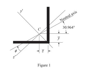
Refer to Figure 1.
Calculate the moment of inertia as shown below.
Along
Along
Consider the angle
Calculate angle
Substitute
Calculate the angle of the neutral axis from the horizontal as shown below.
Calculate the location of the centroid as shown below.
Along y axis:
Along z axis:
Calculate the neutral axis intersects for vertical leg as shown below.
Substitute
Calculate the neutral axis intersects for horizontal leg as shown below.
Substitute
Therefore, the points y and z are located on the neutral axis for the loading P
Want to see more full solutions like this?
Chapter 6 Solutions
Connect 1-semester Access Card For Mechanics Of Materials - 2016 Update


- A 48-kip·in. torque T is applied to each of the cylinders shown. a) For the 3-in. diameter solid cylinder and loading shown, determine the maximum shearing stress. b) Determine the inner diameter of the 4-in. diameter hollow cylinder shown, for which the maximum stress is the same as in part a.arrow_forwardFor the element shown, determine the range of values of τxy for which the maximum in-plane shearing stress is equal to or less than 150 MPa.arrow_forwardFor the state of plane stress shown, determine the largest value of σy for which the maximum in-plane shearing stress is equal to or less than 75 MPaarrow_forward
- Two solid steel shafts are fitted with flanges that are then connected by bolts as shown. The bolts are slightly undersized and permit a 1.5° rotation of one flange with respect to the other before the flanges begin to rotate as a single unit. Knowing that G = 77.2 GPa, determine the maximum shearing stress in each shaft when a torque T of magnitude 500 N·m is applied to the flange indicated.The torque T is applied to flange Barrow_forwardShafts AB and BC are solid, and are exposed to torques that are connected to an elevator.From the loading shown, determine (a) The maximum shearing stress in shaft AB, (b) The maximum shearing stress in shaft BC (c) The smallest diameter of shaft AB for which the maximum value of the shearing stress in the assembly will not increasearrow_forwardA torque of magnitude T=12 kN·m is applied to the end of a tank containing compressed air under a pressure of 8 MPa. Knowing that the tank has a 180-mm inner diameter and a 12-mm wall thickness, determine the maximum normal stress and the maximum in-plane shearing stress in the tank.arrow_forward
- A centric load P is applied to the granite block shown. Knowing that the resulting maximum value of the shearing stress in the block is 2.5 ksi, determine (a) the magnitude of P, (b) the orientation of the surface on which the maximum shearing stress occurs, (c) the normal stress exerted on the surface, (d) the maximum value of the normal stress in the block.arrow_forwardThe solid shaft shown is formed of a brass for which the allowable shearing stress is 55 MPa. Neglecting the effect of stress concentrations, determine the smallest diameters dAB and dBC for which the allowable shearing stress is not exceeded. Take TC = 300 N·m.arrow_forwardThree boards, each of 1.5 x3.5-in. rectangular cross section, are nailed together to form a beam that is subjected to a vertical shear of 250 lb. Knowing that the spacing between each pair of nails is 2.5 in., determine the shearing force in each nail.arrow_forward
- The design specifications of a 2-m-long solid circular transmission shaft require that the angle of twist of the shaft not exceed 3° when a torque of 9 kN·m is applied. Determine the required diameter of the shaft, knowing that the shaft is made of (a) a steel with an allowable shearing stress of 90 MPa and a modulus of rigidity of 77 GPa, (b) a bronze with an allowable shearing stress of 35 MPa and a modulus of rigidity of 42 GPaarrow_forwardKnowing that a given vertical shear V causes a maximum shearing stress of 50 MPa in a thin-walled member having the cross section shown, determine the corresponding shearing stress at (a) point a, (b) point b, (c) point c.arrow_forwardIn the structure shown, an 8 mm diameter pin is used at A, and 12 mm diameter pins are used at B and D. Knowing that the allowable shearing stress is 120 MPa at all connections and that the allowable normal stress and bearing stress is 240 MPa in each of the two links joining B and D, determine the allowable load Parrow_forward
 Elements Of ElectromagneticsMechanical EngineeringISBN:9780190698614Author:Sadiku, Matthew N. O.Publisher:Oxford University Press
 Mechanics of Materials (10th Edition)Mechanical EngineeringISBN:9780134319650Author:Russell C. HibbelerPublisher:PEARSON
 Thermodynamics: An Engineering ApproachMechanical EngineeringISBN:9781259822674Author:Yunus A. Cengel Dr., Michael A. BolesPublisher:McGraw-Hill Education
 Control Systems EngineeringMechanical EngineeringISBN:9781118170519Author:Norman S. NisePublisher:WILEY
 Mechanics of Materials (MindTap Course List)Mechanical EngineeringISBN:9781337093347Author:Barry J. Goodno, James M. GerePublisher:Cengage Learning
 Engineering Mechanics: StaticsMechanical EngineeringISBN:9781118807330Author:James L. Meriam, L. G. Kraige, J. N. BoltonPublisher:WILEY