
Concept explainers
Videos
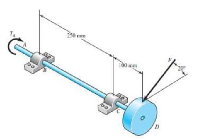
The rotating solid steel shaft is simply supported by bearings at points B and C and is driven by a gear (not shown) which meshes with the spur gear at D. which has a 150-mm pitch diameter. The force F from the drive gear acts at a pressure angle of 20°. The shaft transmits a torque to point A of TA = 340 N · m. The shaft is machined from steel with Sy = 420 MPa and Sut = 560 MPa. Using a factor of safety of 2.5, determine the minimum allowable diameter of the 250-mm section of the shaft based on (a) a static yield analysis using the distortion energy theory and (b) a fatigue-failure analysis. Assume sharp fillet radii at the bearing shoulders for estimating stress-concentration factors.

Trending nowThis is a popular solution!

Chapter 7 Solutions
SHIGLEY'S MECH.ENGINEERING DESIGN-EBK>I


- The shafts are made of steel with shear modulus of 75 GPa. Determine the angle of twist of gear B if a torque of 30 kN·m is applied to gear B. Both shafts have the same diameter of 90 mm. (Hint: for the meshing cylindrical gears, i.e. gear C and D, the angle of twist need to time the radius of the gear while applying the equation of compatibility.)arrow_forwardIn the gear system shown, the motor applies a 190 lb-ft torque to the gear at A. A torque of Tc = 392 lb-ft is removed from the shaft at gear C, and the remaining torque is removed at gear D. Assume that DA-4-in.-diameter, Dg=12-in.-diameter, L₁=56 in., and L₂-30 in. Segments (1) and (2) are solid 1.5-in.-diameter steel [G = 12200 ksi] shafts, and the bearings shown allow free rotation of the shaft. Determine: (a) the maximum shear stresses T₁, T₂ in segments (1) and (2) of the shaft. (b) the rotation angle D/B of gear D relative to gear B. Answers: (a) T₁ (b) D/B = = i ᎠᏴ ; A DA i B L₁ Tc amala ksi, T₂ = L2 i Tp D ksi.arrow_forwardTORSION An aluminum shaft with a constant diameter of 70 mm is loaded by torques applied to gears attached to it. Use G = 28 GPa. DETERMINE: A. the relative angle of twist of gear D relative to gear A (in degrees) B. the direction of the rotation of A relative to D? PROVIDE FBDarrow_forward
- Calculate the angle of twist at point A. A for the following diagrammed problem. There is a 1600 lb-in torque T applied at A. Shaft AB is 12 in. long, and shaft CD is 8 in. long. Gear B has 8 in. diameter, and Gear C has 5 in. diameter. Both shafts have diameter 1 in. Assume that there is no slip between the gears, and that all components are made of steel with shear modulus G-29 × 10° psi. TA = 1600 lb in A 12 in B C 8 in Darrow_forwardA steel shaft ABCD having a total length of 3.5 m consists of three lengths having different sections as follows: AB is hollow having outside and inside diameters of 100 mm and 62.5 mm respectively, and BC and CD are solid. BC has a diameter of 100 mm and CD has a diameter of 87.5 mm. If the angle of twist is the same for each section, Calculate the length of each section, l1, l2 and l3. Analyse the value of the applied torque and the total angle of twist, if the maximum shear stress in the hollow portion is PP MPa and shear modulus, G = QQ GPa. PP=75MPA Please refer appendix for PP and QQ values. QQ=88GPA в C D 62.5 mm 100 mm 100 mm 87.5 mm 13 3.5 marrow_forwardShafts ab and ce are support by pillow bearing blocks as shown. Compute the angle of twist at point a. Report your answer in degrees to two decimal places. 35 in A Y bearing bearing gear c: radius 2.0 in 2 in-k gear b: shaft ab: shaft ce: radius 5.0 in b a radius 0.5 in 5 in-k radius = 0.7 in d. bearing e bearing all shafts: G = 12000 ksi 25 in 30 inarrow_forward
- The two solid steel shafts shown in the figure are connected by gears. Determine the angle of twist of end A of shaft AB when the torque T = 25 N - m is applied. The DC axis is fixed at D. Each axis has a diameter of 20 mm. G = 70GPa.arrow_forwardA transmission shaft supporting a helical gear B and an overhung bevel gear D is shown in Figure. The shaft is mounted on two bearings, A and C. The pitch circle diameter of the helical gear is 450 mm and the diameter of the bevel gear at the forces is 450 mm. Power is transmitted from the helical gear to the bevel gear. The gears are keyed to the shaft. The material of the shaft is steel 45C8 (ou = 750 N/mm?). The factors kp and k; of ASME code are 2.0 and 1.5 respectively. Determine the shaft diameter using the ASME code. 400 400 400 270 250, 640 210 640 100arrow_forwardConsider two steel shafts CFG and HJ of diameters 50 mm and 70 mm respectively as shown in fig. The shaft CFG is supported at two bearings, while shaft HJ is fixed at 'H' and supported by bearings at 'J. Determine the torques T 1 and T 2 if the twisting at gears C and G is required to be 0.05 rad. Take E=205GPA, G=70GPA 600 mm 75mm 600 mm 50mm 800mm G. T2arrow_forward
- For the shaft shown in the figure below, compute the angle of twist of pulleys B and C relative to A. The steel shaft has a diameter of 35 mm throughout its length. The torques are T1= 1500 N · m, T2 = 1000 N · m, = 500 N · m. The lengths are L, = 500 mm, L2 = 800 mm. T3 L2 T |T2 T3 A C B.arrow_forwardA motor driving a solid circular steel shaft transmits 85 horsepower to a gear at point B (see sketch below). The allowable shear stress in the steel shaft is 6000 pounds per square inch. Determine: The minimum diameter d of the shaft if the shaft is operated at 1350 rpm (revolutions per minute). If the shaft transmits the same power (85 horsepower) at 3500 rpm, will the shaft diameter be larger or smaller than the required diameter of part 1.arrow_forwardA transmission shaft supporting a helical gear B and an overhung bevel gear D is shown in Fig. bearings, A and C. The pitch circle diameter of the helical gear is 450 mm and the diameter of the bevel gear at the forces is 450 mm. Power is transmitted from the helical gear to the bevel gear. The gears are keyed to the shaft. The material of the shaft is steel 45C8 The factors k, and k, of ASME code are 2.0 and 1.5 respectively. Determine the shaft diameter using the ASME code. 400 The shaft is mounted on two 400 400 270 250 210 640i ]640 100arrow_forward
 Elements Of ElectromagneticsMechanical EngineeringISBN:9780190698614Author:Sadiku, Matthew N. O.Publisher:Oxford University Press
 Mechanics of Materials (10th Edition)Mechanical EngineeringISBN:9780134319650Author:Russell C. HibbelerPublisher:PEARSON
 Thermodynamics: An Engineering ApproachMechanical EngineeringISBN:9781259822674Author:Yunus A. Cengel Dr., Michael A. BolesPublisher:McGraw-Hill Education
 Control Systems EngineeringMechanical EngineeringISBN:9781118170519Author:Norman S. NisePublisher:WILEY
 Mechanics of Materials (MindTap Course List)Mechanical EngineeringISBN:9781337093347Author:Barry J. Goodno, James M. GerePublisher:Cengage Learning
 Engineering Mechanics: StaticsMechanical EngineeringISBN:9781118807330Author:James L. Meriam, L. G. Kraige, J. N. BoltonPublisher:WILEY