
Vector Mechanics for Engineers: Statics
12th Edition
ISBN: 9781259977268
Author: Ferdinand P. Beer, E. Russell Johnston Jr., David Mazurek
Publisher: McGraw-Hill Education
expand_more
expand_more
format_list_bulleted
Videos
Textbook Question
Chapter 7.1, Problem 7.13P
The axis of the curved member AB is a parabola with vertex at A. If a vertical load P of magnitude 450 lb is applied at A, determine the internal forces at J when h = 12 in., L = 40 in., and a = 24 in.
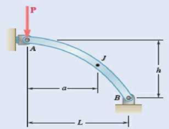
Fig. P7.13 and P7.14
Expert Solution & Answer
Want to see the full answer?
Check out a sample textbook solution
Students have asked these similar questions
Each of the four vertical Ilinks has an 8 x 36-mm uniform rectangular cross section and each of the four pins has a 16-mm diameter. Take P= 19 kN. 0.4 m C 0.25 m 0.2 m B. P Determine the average bearing stress at Bin member ABC, knowing that this member has a 10 x 50-mm uniform rectangular cross section. MPa. The average bearing stress at Bin member ABC is.
A 40-kN axial load is applied to a short wooden post that is supported by a concrete footing resting on undisturbed soil. Determine (a) the maximum bearing stress on the concrete footing, (b) the size of the footing for which the average bearing stress in the soil is 145 kPa.
A vibration isolation unit consists of two blocks of hard rubber with a modulus of rigidity G= 19 MPa bonded to a plate AB and to rigid supports as shown. Denoting by P the magnitude of the force applied to the plate and by δ the corresponding deflection, determine the effective spring constant, k 5 P/δ, of the system.
Chapter 7 Solutions
Vector Mechanics for Engineers: Statics
Ch. 7.1 - 7.1 and 7.2 Determine the internal forces (axial...Ch. 7.1 - Prob. 7.2PCh. 7.1 - Determine the internal forces at point J when =...Ch. 7.1 - Fig. P7.3 and P7.4 7.4 Determine the internal...Ch. 7.1 - Determine the internal forces at point J when =...Ch. 7.1 - Fig. P7.5 and P7.6 7.6 Determine the internal...Ch. 7.1 - An archer aiming at a target is pulling with a...Ch. 7.1 - For the bow of Prob. 7.7, determine the magnitude...Ch. 7.1 - A semicircular rod is loaded as shown. Determine...Ch. 7.1 - A semicircular rod is loaded as shown. Determine...
Ch. 7.1 - A semicircular rod is loaded as shown. Determine...Ch. 7.1 - Fig. P7.11 and P7.12 7.12 A semicircular rod is...Ch. 7.1 - The axis of the curved member AB is a parabola...Ch. 7.1 - Knowing that the axis of the curved member AB is a...Ch. 7.1 - Knowing that the radius of each pulley is 120 mm...Ch. 7.1 - Fig. P7.15 and P7.16 7.16 Knowing that the radius...Ch. 7.1 - A 5-in.-diameter pipe is supported every 9 ft by a...Ch. 7.1 - For the frame of Prob. 7.17, determine the...Ch. 7.1 - Knowing that the radius of each pulley is 200 mm...Ch. 7.1 - Fig. P7.19 and P7.20 7.20 Knowing that the radius...Ch. 7.1 - and 7.22 A force P is applied to a bent rod that...Ch. 7.1 - and 7.22 A force P is applied to a bent rod that...Ch. 7.1 - A quarter-circular rod of weight W and uniform...Ch. 7.1 - For the rod of Prob. 7.23, determine the magnitude...Ch. 7.1 - A semicircular rod of weight W and uniform cross...Ch. 7.1 - A semicircular rod of weight W and uniform cross...Ch. 7.1 - 7.27 and 7.28 A half section of pipe rests on a...Ch. 7.1 - 7.27 and 7.28 A half section of pipe rests on a...Ch. 7.2 - 7.29 through 7.32 For the beam and loading shown,...Ch. 7.2 - 7.29 through 7.32 For the beam and loading shown,...Ch. 7.2 - 7.29 through 7.32 For the beam and loading shown,...Ch. 7.2 - 7.29 through 7.32 For the beam and loading shown,...Ch. 7.2 - 7.33 and 7.34 For the beam and loading shown, (a)...Ch. 7.2 - 7.33 and 7.34 For the beam and loading shown, (a)...Ch. 7.2 - 7.35 and 7.36 For the beam and loading shown, (a)...Ch. 7.2 - 7.35 and 7.36 For the beam and loading shown, (a)...Ch. 7.2 - 7.37 and 7.38 For the beam and loading shown, (a)...Ch. 7.2 - 7.37 and 7.38 For the beam and loading shown, (a)...Ch. 7.2 - For the beam and loading shown, (a) draw the shear...Ch. 7.2 - For the beam and loading shown, (a) draw the shear...Ch. 7.2 - For the beam and loading shown, (a) draw the shear...Ch. 7.2 - For the beam and loading shown, (a) draw the shear...Ch. 7.2 - Assuming the upward reaction of the ground on beam...Ch. 7.2 - Solve Problem 7.43 knowing that P = 3wa. PROBLEM...Ch. 7.2 - Assuming the upward reaction of the ground on beam...Ch. 7.2 - Solve Prob. 7.45 assuming that the 12-kip load has...Ch. 7.2 - Assuming the upward reaction of the ground on beam...Ch. 7.2 - Prob. 7.48PCh. 7.2 - Draw the shear and bending-moment diagrams for the...Ch. 7.2 - Draw the shear and bending-moment diagrams for the...Ch. 7.2 - Draw the shear and bending-moment diagrams for the...Ch. 7.2 - Draw the shear and bending-moment diagrams for the...Ch. 7.2 - Two small channel sections DF and EH have been...Ch. 7.2 - Solve Prob. 7.53 when = 60. PROBLEM 7.53 Two...Ch. 7.2 - For the structural member of Prob. 7.53, determine...Ch. 7.2 - For the beam of Prob. 7.43, determine (a) the...Ch. 7.2 - Determine (a) the distance a for which the maximum...Ch. 7.2 - For the beam and loading shown, determine (a) the...Ch. 7.2 - A uniform beam is to be picked up by crane cables...Ch. 7.2 - Knowing that P = Q = 150 lb, determine (a) the...Ch. 7.2 - Knowing that P = Q = 150 lb, determine (a) the...Ch. 7.2 - In order to reduce the bending moment in the...Ch. 7.3 - Using the method of Sec. 7.3, solve Prob. 7.29....Ch. 7.3 - Prob. 7.64PCh. 7.3 - Using the method of Sec. 7.3, solve Prob. 7.31....Ch. 7.3 - Prob. 7.66PCh. 7.3 - Using the method of Sec. 7.3, solve Prob. 7.33....Ch. 7.3 - Using the method of Sec. 7.3, solve Prob. 7.34....Ch. 7.3 - 7.69 and 7.70 For the beam and loading shown, (a)...Ch. 7.3 - 7.69 and 7.70 For the beam and loading shown, (a)...Ch. 7.3 - Using the method of Sec. 7.3, solve Prob. 7.39....Ch. 7.3 - Using the method of Sec. 7.3, solve Prob. 7.40....Ch. 7.3 - Using the method of Sec. 7.3, solve Prob. 7.41....Ch. 7.3 - Using the method of Sec. 7.3, solve Prob. 7.42....Ch. 7.3 - 7.75 and 7.76 For the beam and loading shown, (a)...Ch. 7.3 - Prob. 7.76PCh. 7.3 - For the beam and loading shown, (a) draw the shear...Ch. 7.3 - For the beam and loading shown, (a) draw the shear...Ch. 7.3 - For the beam and loading shown, (a) draw the shear...Ch. 7.3 - For the beam and loading shown, (a) draw the shear...Ch. 7.3 - For the beam and loading shown, (a) draw the shear...Ch. 7.3 - For the beam and loading shown, (a) draw the shear...Ch. 7.3 - (a) Draw the shear and bending-moment diagrams for...Ch. 7.3 - Solve Prob. 7.83 assuming that the 300-lb force...Ch. 7.3 - For the beam and loading shown, (a) write the...Ch. 7.3 - For the beam and loading shown, (a) write the...Ch. 7.3 - For the beam and loading shown, (a) write the...Ch. 7.3 - For the beam and loading shown, (a) write the...Ch. 7.3 - The beam AB supports the uniformly distributed...Ch. 7.3 - Solve Prob. 7.89 assuming that the uniformly...Ch. 7.3 - The beam AB is subjected to the uniformly...Ch. 7.3 - Prob. 7.92PCh. 7.4 - Three loads are suspended as shown from the cable...Ch. 7.4 - Knowing that the maximum tension in cable ABCDE is...Ch. 7.4 - If dA = 8 ft and dc = 10 ft, determine the...Ch. 7.4 - Prob. 7.96PCh. 7.4 - Knowing that dc = 5 m, determine (a) the distances...Ch. 7.4 - Prob. 7.98PCh. 7.4 - Knowing that dc = 9 ft, determine (a) the...Ch. 7.4 - Prob. 7.100PCh. 7.4 - Knowing that mB = 70 kg and mC = 25 kg, determine...Ch. 7.4 - Fig. P7.101 and P7.102 7.102 Knowing that mB = 18...Ch. 7.4 - Cable ABC supports two loads as shown. Knowing...Ch. 7.4 - Prob. 7.104PCh. 7.4 - If a = 3 m, determine the magnitudes of P and Q...Ch. 7.4 - If a = 4 m, determine the magnitudes of P and Q...Ch. 7.4 - An electric wire having a mass per unit length of...Ch. 7.4 - The total mass of cable ACB is 20 kg. Assuming...Ch. 7.4 - The center span of the George Washington Bridge,...Ch. 7.4 - The center span of the Verrazano-Narrows Bridge...Ch. 7.4 - Each cable of the Golden Gate Bridge supports a...Ch. 7.4 - Two cables of the same gauge are attached to a...Ch. 7.4 - A 76-m length of wire having a mass per unit...Ch. 7.4 - A cable of length L + is suspended between two...Ch. 7.4 - The total mass of cable AC is 25 kg. Assuming that...Ch. 7.4 - Cable ACB supports a load uniformly distributed...Ch. 7.4 - Each cable of the side spans of the Golden Gate...Ch. 7.4 - A steam pipe weighing 45 lb/ft that passes between...Ch. 7.4 - A cable AB of span L and a simple beam AB of the...Ch. 7.4 - Making use of the property established in Prob....Ch. 7.4 - 7.120 through 7.123 Making use of the property...Ch. 7.4 - 7.120 through 7.123 Making use of the property...Ch. 7.4 - Prob. 7.123PCh. 7.4 - Prob. 7.124PCh. 7.4 - Using the property indicated in Prob. 7.124,...Ch. 7.4 - If the weight per unit length of the cable AB is...Ch. 7.5 - A 25-ft chain with a weight of 30 lb is suspended...Ch. 7.5 - A 500-ft-long aerial tramway cable having a weight...Ch. 7.5 - A 40-m cable is strung as shown between two...Ch. 7.5 - A 50-m steel surveying tape has a mass of 1.6 kg....Ch. 7.5 - Prob. 7.131PCh. 7.5 - Prob. 7.132PCh. 7.5 - A 20-m length of wire having a mass per unit...Ch. 7.5 - Determine the sag of a 30-ft chain that is...Ch. 7.5 - Prob. 7.135PCh. 7.5 - Prob. 7.136PCh. 7.5 - A cable weighing 2 lb/ft is suspended between two...Ch. 7.5 - Prob. 7.138PCh. 7.5 - Prob. 7.139PCh. 7.5 - Fig. P7.139 and P7.140 7.140 A motor M is used to...Ch. 7.5 - Prob. 7.141PCh. 7.5 - Prob. 7.142PCh. 7.5 - Prob. 7.143PCh. 7.5 - Prob. 7.144PCh. 7.5 - To the left of point B, the long cable ABDE rests...Ch. 7.5 - Fig. P7.145 and P7.146 7.146 To the left of point...Ch. 7.5 - The 10-ft cable AB is attached to two collars as...Ch. 7.5 - Prob. 7.148PCh. 7.5 - Prob. 7.149PCh. 7.5 - (a) Determine the maximum allowable horizontal...Ch. 7.5 - A cable has a mass per unit length of 3 kg/m and...Ch. 7.5 - Determine the sag-to-span ratio for which the...Ch. 7.5 - Prob. 7.153PCh. 7 - Knowing that the turnbuckle has been tightened...Ch. 7 - Knowing that the turnbuckle has been tightened...Ch. 7 - Two members, each consisting of a straight and a...Ch. 7 - Knowing that the radius of each pulley is 150 mm,...Ch. 7 - For the beam shown, determine (a) the magnitude P...Ch. 7 - For the beam and loading shown, (a) draw the shear...Ch. 7 - For the beam and loading shown, (a) draw the shear...Ch. 7 - For the beam shown, draw the shear and...Ch. 7 - The beam AB, which lies on the ground, supports...Ch. 7 - Two loads are suspended as shown from the cable...Ch. 7 - A wire having a mass per unit length of 0.65 kg/m...Ch. 7 - A 10-ft rope is attached to two supports A and B...
Knowledge Booster


Learn more about
Need a deep-dive on the concept behind this application? Look no further. Learn more about this topic, mechanical-engineering and related others by exploring similar questions and additional content below.Similar questions
- A 2-m length of an aluminum pipe of 240-mm outer diameter and 10-mm wall thickness is used as a short column to carry a 640-kN centric axial load. Knowing that E= 73 GPa and ν=0.33, determine (a) the change in length of the pipe, (b) the change in its outer diam-eter, (c) the change in its wall thicknessarrow_forwardA cable AB of span L and a simple beam A'B' of the same span are subjected to identical vertical loadings as shown. Show that the magnitude of the bending moment at a point C' in the beam is equal to the product T0h, where T0 is the magnitude of the horizontal component of the tension force in the cable and h is the vertical distance between point C and the chord joining the points of support A and B.arrow_forwardThe length of the 332332 -in.-diameter steel wire CD has been adjusted so that with no load applied, a gap of 116116 in. exists between the end B of the rigid beam ACB and contact point E. Knowing that E = 29 × 106 psi, determine where a 57-lb (w) block should be placed on the beam in order to cause contact between B and E. For contact, x < in.arrow_forward
- Determine the largest axial load P that can be safely supported by a flat steel bar consisting of two portions, both 10 mm thick and, respectively, 40 and 60 mm wide, connected by fillets of radius r=8 mm. Assume an allowable normal stress of 165 MPa.arrow_forwardA load P is supported as shown by a steel pin that has been inserted in a short wooden member hanging from the ceiling. The ultimate strength of the wood used is 60 MPa in tension and 7.5 MPa in shear,while the ultimate strength of the steel is 145 MPa in shear. Knowing that b = 40 mm, c = 55 mm, and d = 12 mm, determine the load P if an overall factor of safety of 3.2 is desired.arrow_forwardColumn ABC has a uniform rectangular cross section and is braced in the xz plane at its midpoint C. (a) Determine the ratio b/d for which the factor of safety is the same with respect to buckling in the xz and yz planes. (b) Using the ratio found in part a, design the cross section of the column so that the factor of safety will be 3.0 when P= 4.4 kN, L=1 m, and E=200 GPaarrow_forward
- 6. A strain gage located at C on the surface of bone AB indicates that the average normal stress in the bone is 3.80 MPa when the bone is subjected to two 1200-N forces as shown. Assuming the cross section of the bone at C to be annular and knowing that its outer diameter is 25 mm, determine the inner diameter of the bone’s cross section at C.arrow_forwardColumn ABC has a uniform rectangular cross section with b=12 mm and d=22 mm. The column is braced in the xz plane at its midpoint C and carries a centric load P of magnitude 3.8 kN. Knowing that a factor of safety of 3.2 is required, determine the largest allowable length L. Use E=200 GPaarrow_forwardA rectangular cross section steel column of length L, a fixed end at B and supports a concentric load at A as shown. Point A is restrained from moving in one of the vertical planes of symmetry of the column, but allows to move in the other plane by the use of two smooth and rounded fixed plates.(a) Determine the ratio a/b of the two sides of the cross section corresponding to the most efficient design against buckling.(b) Design the most efficient cross section for the column, knowing that L = 45 in., E = 10 x 106 psi, P = 20 kips, and that a factor of safety of 2.7 is required. Answers: (a) _______ (b) _______arrow_forward
- A fabric used in air-inflated structures is subjected to a biaxial loading that results in normal stresses ox = 18 ksi and oz = 24 ksi.Knowing that the properties of the fabric can be approximated as E = 12.6 x 10 psi and v = 0.34, determine the change in length of (a) side AB, (b) side BC, (c) diagonal AC.arrow_forwardStraight rods of 0.30-in. diameter and 200-ft length are sometimes used to clear underground conduits of obstructions or to thread wires through a new conduit. The rods are made of high-strength steel and, for storage and transportation, are wrapped on spools of 5-ft diameter. Assuming that the yield strength is not exceeded, determine (a) the maximum stress in a rod, when the rod, which was initially straight, is wrapped on the spool, (b) the corresponding bending moment in the rod. Use E= 29 * 106 psi.arrow_forwardTwo cylindrical rods, one of steel and the other of brass, are joined at C and restrained by rigid supports at A and E. The steel rod has a length of 300 mm while the brass rod has a length of 200 mm. The diameters of the rods are shown in the figure below. A force of 60 kN is applied at point B of the steel segment. For the loading shown and knowing that modulus of elasticity values for steel and brass are respectively Es = 200 GPa and Eb = 105 GPa, determine a.) The reactions at A and E: RA and RE. b.) The deflection of point C from its original location. how to doarrow_forward
arrow_back_ios
SEE MORE QUESTIONS
arrow_forward_ios
Recommended textbooks for you
 Elements Of ElectromagneticsMechanical EngineeringISBN:9780190698614Author:Sadiku, Matthew N. O.Publisher:Oxford University Press
 Mechanics of Materials (10th Edition)Mechanical EngineeringISBN:9780134319650Author:Russell C. HibbelerPublisher:PEARSON
 Thermodynamics: An Engineering ApproachMechanical EngineeringISBN:9781259822674Author:Yunus A. Cengel Dr., Michael A. BolesPublisher:McGraw-Hill Education
 Control Systems EngineeringMechanical EngineeringISBN:9781118170519Author:Norman S. NisePublisher:WILEY
 Mechanics of Materials (MindTap Course List)Mechanical EngineeringISBN:9781337093347Author:Barry J. Goodno, James M. GerePublisher:Cengage Learning
 Engineering Mechanics: StaticsMechanical EngineeringISBN:9781118807330Author:James L. Meriam, L. G. Kraige, J. N. BoltonPublisher:WILEY
Elements Of Electromagnetics
Mechanical Engineering
ISBN:9780190698614
Author:Sadiku, Matthew N. O.
Publisher:Oxford University Press
Mechanics of Materials (10th Edition)
Mechanical Engineering
ISBN:9780134319650
Author:Russell C. Hibbeler
Publisher:PEARSON
Thermodynamics: An Engineering Approach
Mechanical Engineering
ISBN:9781259822674
Author:Yunus A. Cengel Dr., Michael A. Boles
Publisher:McGraw-Hill Education
Control Systems Engineering
Mechanical Engineering
ISBN:9781118170519
Author:Norman S. Nise
Publisher:WILEY
Mechanics of Materials (MindTap Course List)
Mechanical Engineering
ISBN:9781337093347
Author:Barry J. Goodno, James M. Gere
Publisher:Cengage Learning
Engineering Mechanics: Statics
Mechanical Engineering
ISBN:9781118807330
Author:James L. Meriam, L. G. Kraige, J. N. Bolton
Publisher:WILEY
How to balance a see saw using moments example problem; Author: Engineer4Free;https://www.youtube.com/watch?v=d7tX37j-iHU;License: Standard Youtube License