Vector Mechanics for Engineers: Statics
12th Edition
ISBN: 9781259977268
Author: Ferdinand P. Beer, E. Russell Johnston Jr., David Mazurek
Publisher: McGraw-Hill Education
bartleby

Videos

Textbook Question
Book Icon
Chapter 7.4, Problem 7.125P

Using the property indicated in Prob. 7.124, determine the curve assumed by a cable of span L and sag h carrying a distributed load w = w0 cos (πx/L), where x is measured from mid-span. Also determine the maximum and minimum values of the tension in the cable.

PROBLEM 7.124 Show that the curve assumed by a cable that carries a distributed load w(x) is defined by the differential equation d2y/dx2 = w(x)/T0, where T0 is the tension at the lowest point.

Expert Solution & Answer
Check Mark
To determine

The expression for the curve made by the cable, maximum and minimum values of the tension in the cable.

Answer to Problem 7.125P

The curve represented by the cable is (w0L2T0π2)(1cosπxL)_, the minimum tension on the cable is w0L2T0π2_ and maximum tension on the cable is (w0Lπ)1+(Lπh)2_.

Explanation of Solution

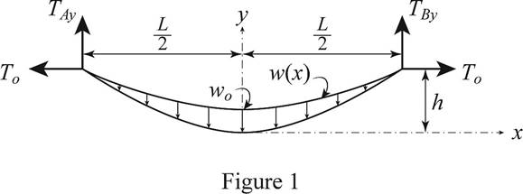
The figure 1 below shows the cable and which makes the curve due the load w.

Vector Mechanics for Engineers: Statics, Chapter 7.4, Problem 7.125P

Write the expression for the load distributed.

w(x)=w0cosπxL

Refer the problem 77268-7.4-7.124P and writhe the differential equation for the curve.

Write the expression for the differential equation for the curve.

d2ydx2=w(x)T0

Substitute w0cosπxL for w(x) in the above equation to rewrite.

d2ydx2=w0cosπxLT0

Integrate both side of the above equation and apply the condition dydx|x=0=0.

dydx=w0cosπxLT0dx=w0LT0πsinπxL

Integrate the above equation and apply the condition y|x=0=0.

y=(w0LT0π)sinπxLdx=(w0L2T0π2)(cosπxL)+C

Here C is the integration constant.

Apply the condition y|x=0=0 to calculate C.

0=(w0L2T0π2)(cos0)+CC=w0L2T0π2

Substitute w0L2T0π2 for C in the equation for y to rewrite.

y=(w0L2T0π2)(cosπxL)+w0L2T0π2=(w0L2T0π2)(1cosπxL)

At x=L2 the tension on the cable might have minimum value.

Substitute x=L2 in the above equation for y to calculate the minimum tension.

y=(w0L2T0π2)(1cosπL(L2))=(w0L2T0π2)(1cosπ2)=w0L2T0π2

The value of y at x=L2 is same as the sag h.

Rewrite the above equation in terms of h.

h=w0L2T0π2T0=w0L2hπ2

Here T0 is the minimum tension on the cable.

Therefore the minimum tension on the cable is w0L2T0π2.

To find the maximum tension on the cable the slope of the above equation for y at x=L2 which is equal to the ratio TByT0

Here TBy is the y-component of the tension at A.

dydx=TByT0=ddx((w0L2T0π2)(1cosπxL))=(w0L2T0π2)(πL)sinπxLTByT0=(w0LT0π)sinπxL

Substitute x=L2 in the above equation to calculate TBy.

TByT0=(w0LT0π)sinπL(L2)=(w0LT0π)sinπ2=w0LT0π

Rewrite the above equation in terms of TBy.

TBy=(w0LT0π)T0=w0Lπ

Write the expression to calculate the maximum tension on the cable.

Tmax=TBy2+T02

Here Tmax is the maximum tension in the cable.

Substitute w0Lπ for TBy and w0L2hπ2 for T0 in the above equation to calculate Tmax.

Tmax=(w0Lπ)2+(w0L2hπ2)2=(w0Lπ)1+(Lπh)2

Conclusion:

Thus, the curve represented by the cable is (w0L2T0π2)(1cosπxL)_, the minimum tension on the cable is w0L2T0π2_ and maximum tension on the cable is (w0Lπ)1+(Lπh)2_.

Want to see more full solutions like this?

Subscribe now to access step-by-step solutions to millions of textbook problems written by subject matter experts!
Students have asked these similar questions
(a) Determine the maximum allowable horizontal span for a uniform cable with a weight per unit length of w if the tension in the cable is not to exceed a given value Tm. (b) Using the result of part a , determine the maximum span of a steel wire for which w = 0.25 lb/ft and Tm = 8000 lb.
A 500-ft-long aerial tramway cable having a weight per unit length of 2.8 lb/ft is suspended between two points at the same elevation. Knowing that the sag is 125 ft, find (a) the horizontal distance between the supports, (b) the maximum tension in the cable.
Determine the sag of a 30-ft chain that is attached to two points at the same elevation that are 20 ft apart.

Chapter 7 Solutions

Vector Mechanics for Engineers: Statics

Ch. 7.1 - A semicircular rod is loaded as shown. Determine...Ch. 7.1 - Fig. P7.11 and P7.12 7.12 A semicircular rod is...Ch. 7.1 - The axis of the curved member AB is a parabola...Ch. 7.1 - Knowing that the axis of the curved member AB is a...Ch. 7.1 - Knowing that the radius of each pulley is 120 mm...Ch. 7.1 - Fig. P7.15 and P7.16 7.16 Knowing that the radius...Ch. 7.1 - A 5-in.-diameter pipe is supported every 9 ft by a...Ch. 7.1 - For the frame of Prob. 7.17, determine the...Ch. 7.1 - Knowing that the radius of each pulley is 200 mm...Ch. 7.1 - Fig. P7.19 and P7.20 7.20 Knowing that the radius...Ch. 7.1 - and 7.22 A force P is applied to a bent rod that...Ch. 7.1 - and 7.22 A force P is applied to a bent rod that...Ch. 7.1 - A quarter-circular rod of weight W and uniform...Ch. 7.1 - For the rod of Prob. 7.23, determine the magnitude...Ch. 7.1 - A semicircular rod of weight W and uniform cross...Ch. 7.1 - A semicircular rod of weight W and uniform cross...Ch. 7.1 - 7.27 and 7.28 A half section of pipe rests on a...Ch. 7.1 - 7.27 and 7.28 A half section of pipe rests on a...Ch. 7.2 - 7.29 through 7.32 For the beam and loading shown,...Ch. 7.2 - 7.29 through 7.32 For the beam and loading shown,...Ch. 7.2 - 7.29 through 7.32 For the beam and loading shown,...Ch. 7.2 - 7.29 through 7.32 For the beam and loading shown,...Ch. 7.2 - 7.33 and 7.34 For the beam and loading shown, (a)...Ch. 7.2 - 7.33 and 7.34 For the beam and loading shown, (a)...Ch. 7.2 - 7.35 and 7.36 For the beam and loading shown, (a)...Ch. 7.2 - 7.35 and 7.36 For the beam and loading shown, (a)...Ch. 7.2 - 7.37 and 7.38 For the beam and loading shown, (a)...Ch. 7.2 - 7.37 and 7.38 For the beam and loading shown, (a)...Ch. 7.2 - For the beam and loading shown, (a) draw the shear...Ch. 7.2 - For the beam and loading shown, (a) draw the shear...Ch. 7.2 - For the beam and loading shown, (a) draw the shear...Ch. 7.2 - For the beam and loading shown, (a) draw the shear...Ch. 7.2 - Assuming the upward reaction of the ground on beam...Ch. 7.2 - Solve Problem 7.43 knowing that P = 3wa. PROBLEM...Ch. 7.2 - Assuming the upward reaction of the ground on beam...Ch. 7.2 - Solve Prob. 7.45 assuming that the 12-kip load has...Ch. 7.2 - Assuming the upward reaction of the ground on beam...Ch. 7.2 - Prob. 7.48PCh. 7.2 - Draw the shear and bending-moment diagrams for the...Ch. 7.2 - Draw the shear and bending-moment diagrams for the...Ch. 7.2 - Draw the shear and bending-moment diagrams for the...Ch. 7.2 - Draw the shear and bending-moment diagrams for the...Ch. 7.2 - Two small channel sections DF and EH have been...Ch. 7.2 - Solve Prob. 7.53 when = 60. PROBLEM 7.53 Two...Ch. 7.2 - For the structural member of Prob. 7.53, determine...Ch. 7.2 - For the beam of Prob. 7.43, determine (a) the...Ch. 7.2 - Determine (a) the distance a for which the maximum...Ch. 7.2 - For the beam and loading shown, determine (a) the...Ch. 7.2 - A uniform beam is to be picked up by crane cables...Ch. 7.2 - Knowing that P = Q = 150 lb, determine (a) the...Ch. 7.2 - Knowing that P = Q = 150 lb, determine (a) the...Ch. 7.2 - In order to reduce the bending moment in the...Ch. 7.3 - Using the method of Sec. 7.3, solve Prob. 7.29....Ch. 7.3 - Prob. 7.64PCh. 7.3 - Using the method of Sec. 7.3, solve Prob. 7.31....Ch. 7.3 - Prob. 7.66PCh. 7.3 - Using the method of Sec. 7.3, solve Prob. 7.33....Ch. 7.3 - Using the method of Sec. 7.3, solve Prob. 7.34....Ch. 7.3 - 7.69 and 7.70 For the beam and loading shown, (a)...Ch. 7.3 - 7.69 and 7.70 For the beam and loading shown, (a)...Ch. 7.3 - Using the method of Sec. 7.3, solve Prob. 7.39....Ch. 7.3 - Using the method of Sec. 7.3, solve Prob. 7.40....Ch. 7.3 - Using the method of Sec. 7.3, solve Prob. 7.41....Ch. 7.3 - Using the method of Sec. 7.3, solve Prob. 7.42....Ch. 7.3 - 7.75 and 7.76 For the beam and loading shown, (a)...Ch. 7.3 - Prob. 7.76PCh. 7.3 - For the beam and loading shown, (a) draw the shear...Ch. 7.3 - For the beam and loading shown, (a) draw the shear...Ch. 7.3 - For the beam and loading shown, (a) draw the shear...Ch. 7.3 - For the beam and loading shown, (a) draw the shear...Ch. 7.3 - For the beam and loading shown, (a) draw the shear...Ch. 7.3 - For the beam and loading shown, (a) draw the shear...Ch. 7.3 - (a) Draw the shear and bending-moment diagrams for...Ch. 7.3 - Solve Prob. 7.83 assuming that the 300-lb force...Ch. 7.3 - For the beam and loading shown, (a) write the...Ch. 7.3 - For the beam and loading shown, (a) write the...Ch. 7.3 - For the beam and loading shown, (a) write the...Ch. 7.3 - For the beam and loading shown, (a) write the...Ch. 7.3 - The beam AB supports the uniformly distributed...Ch. 7.3 - Solve Prob. 7.89 assuming that the uniformly...Ch. 7.3 - The beam AB is subjected to the uniformly...Ch. 7.3 - Prob. 7.92PCh. 7.4 - Three loads are suspended as shown from the cable...Ch. 7.4 - Knowing that the maximum tension in cable ABCDE is...Ch. 7.4 - If dA = 8 ft and dc = 10 ft, determine the...Ch. 7.4 - Prob. 7.96PCh. 7.4 - Knowing that dc = 5 m, determine (a) the distances...Ch. 7.4 - Prob. 7.98PCh. 7.4 - Knowing that dc = 9 ft, determine (a) the...Ch. 7.4 - Prob. 7.100PCh. 7.4 - Knowing that mB = 70 kg and mC = 25 kg, determine...Ch. 7.4 - Fig. P7.101 and P7.102 7.102 Knowing that mB = 18...Ch. 7.4 - Cable ABC supports two loads as shown. Knowing...Ch. 7.4 - Prob. 7.104PCh. 7.4 - If a = 3 m, determine the magnitudes of P and Q...Ch. 7.4 - If a = 4 m, determine the magnitudes of P and Q...Ch. 7.4 - An electric wire having a mass per unit length of...Ch. 7.4 - The total mass of cable ACB is 20 kg. Assuming...Ch. 7.4 - The center span of the George Washington Bridge,...Ch. 7.4 - The center span of the Verrazano-Narrows Bridge...Ch. 7.4 - Each cable of the Golden Gate Bridge supports a...Ch. 7.4 - Two cables of the same gauge are attached to a...Ch. 7.4 - A 76-m length of wire having a mass per unit...Ch. 7.4 - A cable of length L + is suspended between two...Ch. 7.4 - The total mass of cable AC is 25 kg. Assuming that...Ch. 7.4 - Cable ACB supports a load uniformly distributed...Ch. 7.4 - Each cable of the side spans of the Golden Gate...Ch. 7.4 - A steam pipe weighing 45 lb/ft that passes between...Ch. 7.4 - A cable AB of span L and a simple beam AB of the...Ch. 7.4 - Making use of the property established in Prob....Ch. 7.4 - 7.120 through 7.123 Making use of the property...Ch. 7.4 - 7.120 through 7.123 Making use of the property...Ch. 7.4 - Prob. 7.123PCh. 7.4 - Prob. 7.124PCh. 7.4 - Using the property indicated in Prob. 7.124,...Ch. 7.4 - If the weight per unit length of the cable AB is...Ch. 7.5 - A 25-ft chain with a weight of 30 lb is suspended...Ch. 7.5 - A 500-ft-long aerial tramway cable having a weight...Ch. 7.5 - A 40-m cable is strung as shown between two...Ch. 7.5 - A 50-m steel surveying tape has a mass of 1.6 kg....Ch. 7.5 - Prob. 7.131PCh. 7.5 - Prob. 7.132PCh. 7.5 - A 20-m length of wire having a mass per unit...Ch. 7.5 - Determine the sag of a 30-ft chain that is...Ch. 7.5 - Prob. 7.135PCh. 7.5 - Prob. 7.136PCh. 7.5 - A cable weighing 2 lb/ft is suspended between two...Ch. 7.5 - Prob. 7.138PCh. 7.5 - Prob. 7.139PCh. 7.5 - Fig. P7.139 and P7.140 7.140 A motor M is used to...Ch. 7.5 - Prob. 7.141PCh. 7.5 - Prob. 7.142PCh. 7.5 - Prob. 7.143PCh. 7.5 - Prob. 7.144PCh. 7.5 - To the left of point B, the long cable ABDE rests...Ch. 7.5 - Fig. P7.145 and P7.146 7.146 To the left of point...Ch. 7.5 - The 10-ft cable AB is attached to two collars as...Ch. 7.5 - Prob. 7.148PCh. 7.5 - Prob. 7.149PCh. 7.5 - (a) Determine the maximum allowable horizontal...Ch. 7.5 - A cable has a mass per unit length of 3 kg/m and...Ch. 7.5 - Determine the sag-to-span ratio for which the...Ch. 7.5 - Prob. 7.153PCh. 7 - Knowing that the turnbuckle has been tightened...Ch. 7 - Knowing that the turnbuckle has been tightened...Ch. 7 - Two members, each consisting of a straight and a...Ch. 7 - Knowing that the radius of each pulley is 150 mm,...Ch. 7 - For the beam shown, determine (a) the magnitude P...Ch. 7 - For the beam and loading shown, (a) draw the shear...Ch. 7 - For the beam and loading shown, (a) draw the shear...Ch. 7 - For the beam shown, draw the shear and...Ch. 7 - The beam AB, which lies on the ground, supports...Ch. 7 - Two loads are suspended as shown from the cable...Ch. 7 - A wire having a mass per unit length of 0.65 kg/m...Ch. 7 - A 10-ft rope is attached to two supports A and B...
Knowledge Booster
Background pattern image
Mechanical Engineering
Learn more about
Need a deep-dive on the concept behind this application? Look no further. Learn more about this topic, mechanical-engineering and related others by exploring similar questions and additional content below.
Similar questions
SEE MORE QUESTIONS
Recommended textbooks for you
Text book image
Elements Of Electromagnetics
Mechanical Engineering
ISBN:9780190698614
Author:Sadiku, Matthew N. O.
Publisher:Oxford University Press
Text book image
Mechanics of Materials (10th Edition)
Mechanical Engineering
ISBN:9780134319650
Author:Russell C. Hibbeler
Publisher:PEARSON
Text book image
Thermodynamics: An Engineering Approach
Mechanical Engineering
ISBN:9781259822674
Author:Yunus A. Cengel Dr., Michael A. Boles
Publisher:McGraw-Hill Education
Text book image
Control Systems Engineering
Mechanical Engineering
ISBN:9781118170519
Author:Norman S. Nise
Publisher:WILEY
Text book image
Mechanics of Materials (MindTap Course List)
Mechanical Engineering
ISBN:9781337093347
Author:Barry J. Goodno, James M. Gere
Publisher:Cengage Learning
Text book image
Engineering Mechanics: Statics
Mechanical Engineering
ISBN:9781118807330
Author:James L. Meriam, L. G. Kraige, J. N. Bolton
Publisher:WILEY
Relationship Between Elastic Constants and Connecting Equations; Author: Engineers Academy;https://www.youtube.com/watch?v=whW5PnM7Pug;License: Standard Youtube License