
Videos
Knowing that the radius of each pulley is 120 mm and neglecting friction, determine the internal forces at (a) point C, (b) point J that is 100 mm to the left of C.
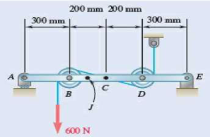
Fig. P7.15 and P7.16
(a)
The internal forces exerted at the point
Answer to Problem 7.15P
The internal forces of shearing force is
Explanation of Solution
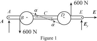
Sketch the free body diagram for the internal forces acting on the frame and pulley system as shown in the Figure 1.
Write the equation of the axial force exerted at the axial point
Here, the force exerted on the frame at the point
Write the equation of the moment of couple formed in the bending moment of the frame and pulley system supported at the point
Here, the axial force exerted on the pulley at point
Write the equation of the axial force exerted at the axial point of the frame from y direction (Refer fig 1).
Here, the axial force exerted on the pulley at point
Sketch the free body diagram for the cable as shown in the Figure 2.
The slope of the cable (Refer fig 2):
The angle formed in the slope of the cable:
Rewrite the above relation to find the angle.
Write the equation of the axial force exerted at the axial point
Here, the angle between the pulley
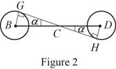
Sketch the free body diagram for the cable for the point
Write the equation of the axial force exerted at the point
Here, shearing force acting on the semicircular rod is
At the pulley
Write the equation of the moment of couple formed in the bending moment supported at the point
Here, the moment of couple exerted at the point
Conclusion:
Substitute
Solve the above equation for
Substitute
Substitute
Substitute
Substitute
The above equation can be written as,
Therefore, the internal forces of shearing force is
(b)
The internal forces exerted at the point
Answer to Problem 7.15P
The internal forces of shearing force is
Explanation of Solution
Sketch the free body diagram for the cable for the point
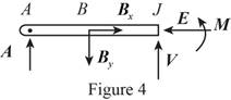
Write the equation of the axial force exerted at the axial point
Here, the force exerted on the frame at the point
Write the equation of the axial force exerted at the axial point of the frame from y direction (Refer fig 4).
Here, the axial force exerted on the pulley at point
Write the equation of the moment of couple formed in the bending moment supported at the point
Here, the moment of couple exerted at the point
Conclusion:
Substitute
Substitute
Substitute
The above equation can be written as,
Therefore, the internal forces of shearing force is
Want to see more full solutions like this?
Chapter 7 Solutions
VECTOR MECH....F/ENGNRS-STATICS -CONNECT
Additional Engineering Textbook Solutions
DeGarmo's Materials and Processes in Manufacturing
Fundamentals of Heat and Mass Transfer
Fluid Mechanics Fundamentals And Applications
INTERNATIONAL EDITION---Engineering Mechanics: Statics, 14th edition (SI unit)
Thinking Like an Engineer: An Active Learning Approach (4th Edition)


- 6.142 A locking C-clamp is used to clamp two pieces of -in. steel plate. Determine the magnitude of the gripping forces produced when two 30-lb forces are applied as shown. -2.6 in.- -1.9 in. -1.3 in.- |30 lb A Bo + 0.85 in. 0.3 in. -2.6 in.- 30 lb 0.8 in. Fig. P6.142arrow_forwardKnowing that a worker applies forces of magnitude P = 135 N to the han- dles, determine the magnitude of the crimping forces that are exerted on the 140 The tool shown is used to crimp terminals onto electric wires. terminal. 30 +40- 200 B D F C E 15 Dimensions in mm -P Fig. P6.140arrow_forwardA 20-m length of wire having a mass per unit length of 0.2 kg/m is attached to a fixed support at A and to a collar at B . Neglecting the effect of friction, determine (a) the sag h for which L = 15m, (b) the corresponding force P.arrow_forward
- The cylinder shown is of weight W and radius r . Express in terms XV and r the magnitude of the largest couple M that can be applied to the cylinder if it is not to rotate, assuming the coefficient of static friction to be (a) zero at A and 0.30 at B, (b) 0.25 at A and 0.30 at B.Fig. P8.18arrow_forward25 mm 60 mm 85 mm D 75 mm 6.136 The tongs shown are used to apply a total upward force of 45 ky on a pipe cap. Determine the forces exerted at D and F on tong ADF. E F 90 mm Fig. P6.136arrow_forward6.42 A floor truss is loaded as shown. Determine the force in 250 lb 500 lb 500 lb 375 lb 250 |b 250 |b 125 ||. 4 ft 4 ft bers CF, EF, and EG. 4 ft 4 ft 4 ft 4 ft E GV B. 2 ft Fig. P6.42 and P6.43arrow_forward
- Problem 10: The 48-kg collar G is released from rest in the position shown and is stopped by plate BDF that is attached to the 20-mm-diameter steel rod CD and to the 15-mm-diameter steel rods AB and EF. Knowing that for the grade of steel used allowable normal stress of 180 MPa and E=200 GPa, determine the largest allowable distance h. ACE 2.5m С D B Farrow_forwardThe frictional resistance of a thrust bearing decreases as the shaft and bearing surfaces wear out. It is generally assumed that the wear is directly proportional to the distance traveled by any given point of the shaft and thus to the distance r from the point to the axis of the shaft. Assuming then that the normal force per unit area is inversely proportional to r , show that the magnitude M of the couple required to overcome the frictional resistance of a worn-out end bearing (with contact over the full circular area) is equal to 75 percent of the value given by Eq. (8.9) for a new bearing.arrow_forward8.37 Bar AB is attached to collars that can slide on the inclined rods 45° shown. A force P is applied at point D located at a distance a from end A. Knowing that the coefficient of static friction m, between each collar and the rod upon which it slides is 0.30 and neglecting the weights of the bar and of the collars, determine the smallest value of the ratio a/L for which equilibrium is maintained. A B Fig. P8.37arrow_forward
- -2 m -2 m – 4.5 kN 1.4 kN E 2.8 kN Do G 0.5 m F 1 kN I kN B 3 m I kN. I kN A |C I 1 m '1m 1 m 1 m Fig. P6.15 and P6.16 6.16 For the Gambrel roof truss shown, determine the force in members CG and CI and in each of the members located to the right of the centerline of the truss. State whether each member is in tension or compression.arrow_forwardQ1: Knowing that the radius of each pulley is 200 mm and neglecting friction, determine the internal forces at points J and K of the frame shown. m В 1.8 m A D K F E +0.2 m 0.8 m 0.8 m 0.2 m 0.6 m 360 Narrow_forwardSituation 10. A single force P acts at Cin a direction perpendicular to the handle BC of the crank shown. Knowing that M, +20 N – m, M, = -8.75 N – m and M, = -30 N – m, determine the magnitude of P and the values of o and 0 %3D 100 mm В 200 mm 150 mm xrarrow_forward
 Elements Of ElectromagneticsMechanical EngineeringISBN:9780190698614Author:Sadiku, Matthew N. O.Publisher:Oxford University Press
 Mechanics of Materials (10th Edition)Mechanical EngineeringISBN:9780134319650Author:Russell C. HibbelerPublisher:PEARSON
 Thermodynamics: An Engineering ApproachMechanical EngineeringISBN:9781259822674Author:Yunus A. Cengel Dr., Michael A. BolesPublisher:McGraw-Hill Education
 Control Systems EngineeringMechanical EngineeringISBN:9781118170519Author:Norman S. NisePublisher:WILEY
 Mechanics of Materials (MindTap Course List)Mechanical EngineeringISBN:9781337093347Author:Barry J. Goodno, James M. GerePublisher:Cengage Learning
 Engineering Mechanics: StaticsMechanical EngineeringISBN:9781118807330Author:James L. Meriam, L. G. Kraige, J. N. BoltonPublisher:WILEY