
Concept explainers
Videos
For the beam shown, draw the shear and bending-moment diagrams, and determine the magnitude and location of the maximum absolute value of the bending moment, knowing that (a) M = 0, (b) M = 24 kip-ft.
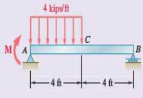
Fig. P7.161
(a)
Plot the shear force and bending moment diagram for the beam.
Find the magnitude and location of the maximum absolute value of the bending moment.
Answer to Problem 7.161RP
The location and magnitude of the maximum absolute bending moment is
Explanation of Solution
Given information:
The moment applied at A is
Calculation:
Show the free-body diagram of the entire beam as in Figure 1.
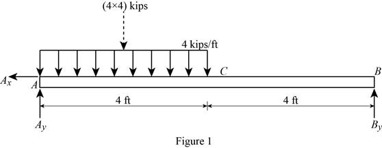
Find the vertical reaction at point B by taking moment about point A.
Find the vertical reaction at point A by reoslving the vertical component of forces.
Resolve the horizontal component of forces.
Consider the section AC:
Consider a section at a distance x from left end A.
Show the free-body diagram of the section as in Figure 2.
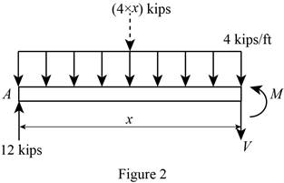
Resolve the vertical component of forces.
Take moment about the section.
At
Substitute 0 for x in Equation (1).
Substitute 0 for x in Equation (2).
At
Substitute 4 ft for x in Equation (1).
Substitute 4 ft for x in Equation (2).
Consider the section CB:
Show the free-body diagram of the section as in Figure 3.
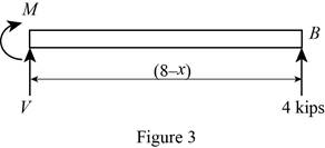
Resolve the vertical component of forces.
Take moment about the section.
At
Substitute 4 ft for x in Equation (3).
At
Substitute 8 ft for x in Equation (3).
Tabulate the shear force values as in Table 1.
| Location, x ft | Shear force, kips |
| 0 | 12 |
| 4 | –4 |
| 8 | –4 |
Plot the shear force diagram as in Figure 4.
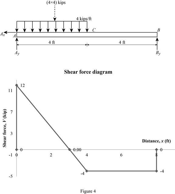
The maximum bending moment occurs where the shear force changes sign.
Refer to the Figure 4, the shear force changes in the section AC.
Substitute 0 for V in Equation (1).
Substitute 3 ft for x in Equaiton (2).
Tabulate the bending moment values as in Table 2.
| Location, x ft | Bending moment, kips-ft |
| 0 | 0 |
| 3 | 18 |
| 4 | 16 |
| 8 | 0 |
Plot the bending moment values as in Figure 5.
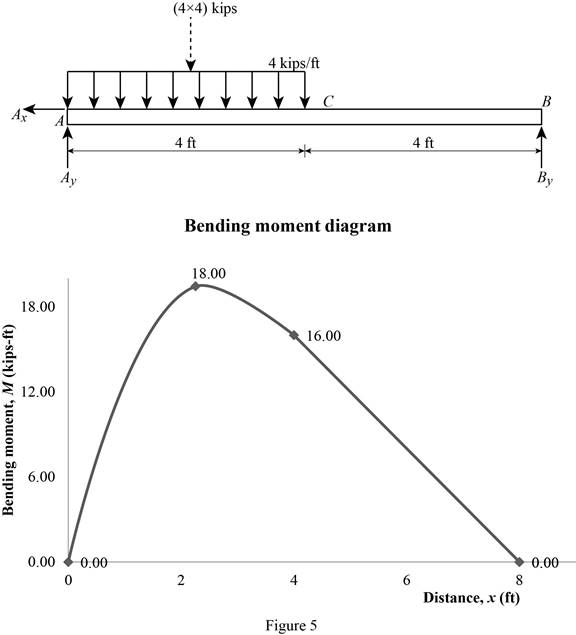
Therefore, the location and magnitude of the maximum absolute bending moment is
(b)
Plot the shear force and bending moment diagram for the beam.
Find the magnitude and location of the maximum absolute value of the bending moment.
Answer to Problem 7.161RP
The location and magnitude of the maximum absolute bending moment is
Explanation of Solution
Given information:
The moment applied at A is
Calculation:
Show the free-body diagram of the entire beam as in Figure 6.
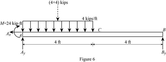
Find the vertical reaction at point B by taking moment about point A.
Find the vertical reaction at point A by reoslving the vertical component of forces.
Resolve the horizontal component of forces.
Consider the section AC:
Consider a section at a distance x from left end A.
Show the free-body diagram of the section as in Figure 7.
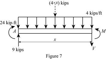
Resolve the vertical component of forces.
Take moment about the section.
At
Substitute 0 for x in Equation (4).
Substitute 0 for x in Equation (5).
At
Substitute 4 ft for x in Equation (4).
Substitute 4 ft for x in Equation (5).
Consider the section CB:
Show the free-body diagram of the section as in Figure 8.
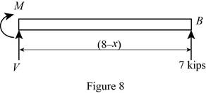
Resolve the vertical component of forces.
Take moment about the section.
At
Substitute 4 ft for x in Equation (6).
At
Substitute 8 ft for x in Equation (6).
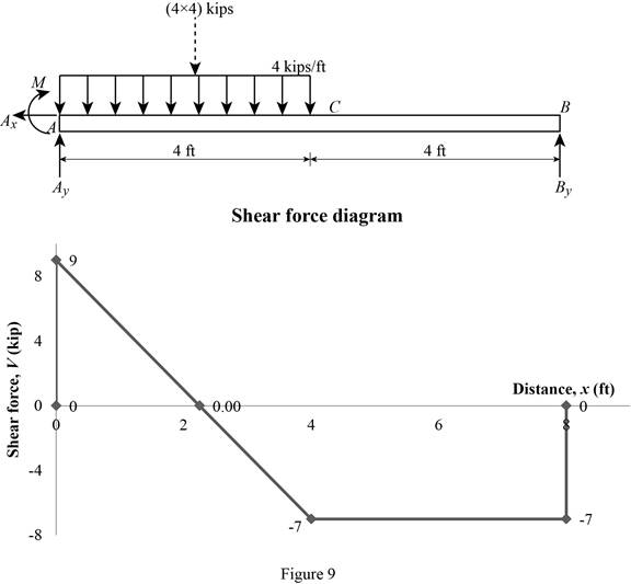
Tabulate the shear force values as in Table 3.
| Location, x ft | Shear force, kips |
| 0 | 9 |
| 4 | –7 |
| 8 | –7 |
Plot the shear force diagram as in Figure 9.
The maximum bending moment occurs where the shear force changes sign.
Refer to the Figure 4, the shear force changes in the section AC.
Substitute 0 for V in Equation (4).
Substitute 2.25 ft for x in Equaiton (5).
Tabulate the bending moment values as in Table 4.
| Location, x ft | Bending moment, kips-ft |
| 0 | 0 |
| 2.25 | 34.125 |
| 4 | 28 |
| 8 | 0 |
Plot the bending moment values as in Figure 10.
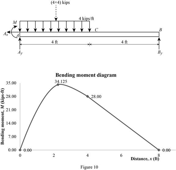
Therefore, the location and magnitude of the maximum absolute bending moment is
Want to see more full solutions like this?
Chapter 7 Solutions
VECTOR MECH....F/ENGNRS-STATICS -CONNECT


- 7.29 through 7.32 For the beam and loading shown, (a) draw the shear and bending-moment diagrams, (b) determine the maximum absolute values of the shear and bending moment. B Fig. P7.31arrow_forward0.6 m 25 kN/m 40 kN 1.8 m 40 KN C 0.6 m D PROBLEM 5.108 (a) Using singularity functions, write the equations for the shear and bending moment for the beam and loading shown. (b) Determine the maximum value of the bending moment in the beam.arrow_forwardKnowing that P= 480 N,Q=320N determine (a) the distance a for which the absolute value of the bending moment in the beam is as small as possible, (b) the corresponding maximum normal stress due to bending.arrow_forward
- Two small channel sections DF and EH have been welded to the uniform beam AB of weight W = 3 kN to form the rigid structural member shown. This member is being lifted by two cables attached at D and E . Knowing that 0= 30° and neglecting the weight of the channel sections, (a) draw the shear and bending-moment diagrams for beam AB, (b) determine the maximum absolute values of the shear and bending moment in the beam.arrow_forwardA cable AB of span L and a simple beam A'B' of the same span are subjected to identical vertical loadings as shown. Show that the magnitude of the bending moment at a point C' in the beam is equal to the product T0h, where T0 is the magnitude of the horizontal component of the tension force in the cable and h is the vertical distance between point C and the chord joining the points of support A and B.arrow_forwardPROBLEMS 5.16, 5.17 Draw the shear and bending- moment diagrams for the beam and loading shown, and determine the maximum absolute value (a) of the shear, and (b) of the bending moment. 68 kN 30 kN/m D -1.2 m 1.2 m 1.2 m- Fig. P5.16 PROBLEM 5.21 For the beam and loading shown, bending stress on a transverse sectiarrow_forward
- PROBLEMS 5.16, 5.17 Draw the shear and bending- moment diagrams for the beam and loading shown, and determine the maximum absolute value (a) of the shear, and (b) of the bending moment. 65 kN 30 kN/m D A -1.2 m→-1.2 m -1.2 m→arrow_forwardKnowing that P=Q= 480 N, determine (a) the distance a for which the absolute value of the bending moment in the beam is as small as possible, (b) the corresponding maximum normal stress due to bending.arrow_forwardDetermine (a) the distance a for which the maximum absolute value of the bending moment in the beam is as small as possible, (b) the corresponding maximum normal stress due to bending.arrow_forward
- PROBLEM 7.40 80 kN NA OE For the beam and loading shown, (a) draw the shear and bending- moment diagrams, (b) detemine the maximum absolute values of the shear and bending moment. D' 3m 2 m 2 m Fig. P7.40arrow_forwardFig. P7.32 A W 2 B 2arrow_forwardA semicircular rod of weight W and uniform cross section is supported as shown. Determine the bending moment at point J w hen 0=60°.Fig. P7.23arrow_forward
 Elements Of ElectromagneticsMechanical EngineeringISBN:9780190698614Author:Sadiku, Matthew N. O.Publisher:Oxford University Press
 Mechanics of Materials (10th Edition)Mechanical EngineeringISBN:9780134319650Author:Russell C. HibbelerPublisher:PEARSON
 Thermodynamics: An Engineering ApproachMechanical EngineeringISBN:9781259822674Author:Yunus A. Cengel Dr., Michael A. BolesPublisher:McGraw-Hill Education
 Control Systems EngineeringMechanical EngineeringISBN:9781118170519Author:Norman S. NisePublisher:WILEY
 Mechanics of Materials (MindTap Course List)Mechanical EngineeringISBN:9781337093347Author:Barry J. Goodno, James M. GerePublisher:Cengage Learning
 Engineering Mechanics: StaticsMechanical EngineeringISBN:9781118807330Author:James L. Meriam, L. G. Kraige, J. N. BoltonPublisher:WILEY