
Videos
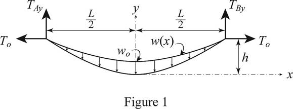
Using the property indicated in Prob. 7.124, determine the curve assumed by a cable of span L and sag h carrying a distributed load w = w0 cos (πx/L), where x is measured from mid-span. Also determine the maximum and minimum values of the tension in the cable.
PROBLEM 7.124 Show that the curve assumed by a cable that carries a distributed load w(x) is defined by the differential equation d2y/dx2 = w(x)/T0, where T0 is the tension at the lowest point.
The expression for the curve made by the cable, maximum and minimum values of the tension in the cable.
Answer to Problem 7.125P
The curve represented by the cable is
Explanation of Solution
The figure 1 below shows the cable and which makes the curve due the load w.
Write the expression for the load distributed.
Refer the problem 77268-7.4-7.124P and writhe the differential equation for the curve.
Write the expression for the differential equation for the curve.
Substitute
Integrate both side of the above equation and apply the condition
Integrate the above equation and apply the condition
Here C is the integration constant.
Apply the condition
Substitute
At
Substitute
The value of y at
Rewrite the above equation in terms of h.
Here
Therefore the minimum tension on the cable is
To find the maximum tension on the cable the slope of the above equation for y at
Here
Substitute
Rewrite the above equation in terms of
Write the expression to calculate the maximum tension on the cable.
Here
Substitute
Conclusion:
Thus, the curve represented by the cable is
Want to see more full solutions like this?
Chapter 7 Solutions
VECTOR MECH....F/ENGNRS-STATICS -CONNECT


- A 10-H boom is acted upon by the 500 lb force shown. Determine the tension in each cable. 6 ft 4 ft D. В 7 ft 6 ft. 4 ft 500 lbarrow_forwardNOTE: This is a multi-part question. Once an answer is submitted, you will be unable to return to this part. Three wires are connected at point D, which is located 18 in. below the T-shaped pipe support ABC. Determine the tension in each wire when a 180-lb cylinder is suspended from point Das shown in the diagram. 24 in. В 16 in. 24 in. 22 in. A 18 in. D W Ib The tension in wire DA is Ib. The tension in wire DB is Ib. The tension in wire DC is Ib.arrow_forwardSituation 2. Determine the maximum weight of the bucket that the wire can support so that no single wire develops a tension exceeding 100 Ib. B ,30° 30°arrow_forward
- A transmission tower is held by three guy wires attached to a pin at A and anchored by bolts at B, C, and D. If the tension in wire AC is 413 Ib, determine the vertical force P exerted by the tower on the pin at A. 100 ft D 20 ft 25 ft B 74 ft 20 ft 60 ft `18 ft The vertical force P exerted by the tower on the pin at A is Ib.arrow_forwardIf dC, = 15 ft. determine (a) : the distances dB and dD, (b) the inuximum tension in the cable.Fig. 7.99arrow_forward5. Determine the forces in each cable if P = 10KN. 6 ft 3 ft D 7.5 ft 6.5 ft 4.5 ft |B 6 ftarrow_forward
- 2. A load of 100 lbs is hung from the middle of a rope, which is stretched between two rigid walls 30 ft apart. Due to the load, the rope sags 4 feet in the middle. Determine the tension in the rope.arrow_forwardQ.3) The cable shown below is supported by two pins at A and B. The maximum cable tension due to the applied forces is 1000 lb. Determine the tensions in all four segments of the cable and the sags of the load points P1, P2, and P3. В 5 ft- 3 ft А. 2 ft 4 ft 6 ft P3 P1 y V P2 300 lb 100 lb 200 lbarrow_forward8:05 76% 2 15° 25° T2 B A telephone cable is clamped at A to the pole AB. Knowing that the tension in the right-hand portion of the cable is T, = 1000 Īb, deter- mine by trigonometry (a) the required tension T¡ in the left-hand portion if the resultant R of the forces exerted by the cable at A is to be vertical, (b) the corresponding magnitude of R. 3 A steel tank is to be positioned in an excavation. Knowing that the magnitude of P= 500 lb, determine the required angle a if the resultant R of the two forces applied at A is to be vertical. Also, determine the corresponding magnitude R. 425 lb 30° 4 Two forces P and Q are applied to the lid of a storage bin as shown. Knowing that P =60 N and Q = 48 N, determine the magnitude and direction of the resultant of the two forces. 85° 55° 25° Reference: Beer, F. P., Johnston, E. R. J., Mazurek, D. F., Cornwell, P. J., & Self, B. P. (2016). Vector Mechanics For Engineers Statics and Dynamics (11th ed.). New York: McGraw-Hill Education.arrow_forward
- Problem 1.- A stake is being pulled out of the ground by means of two ropes as shown. Knowing that the tension in one rope is 120 N, determine by trigonometry the magnitude and direction of the force P so that the resultant is a vertical force of 160 N. Answer: P = 72.1 N and a = 44.7° %3D 120 N 25arrow_forwardThe 50-kg plate ABCD is supported by hinges along edge AB and by wire ED (assuming that wire CE in the figure is replaced by a wire connecting E and D). Knowing that the plate is uniform, determine the tension in the wire. (Assume that wire CE is replaced by a wire connecting E and D.) D = 200 mm! 400 mm 480 mm y 240 mm A 3 of 3 240 mm E 400 mm 200 mm B xarrow_forwardCalculate the forces in members AB, BH, and BG. Members BF and CG are cables which can support tension only. Forces are positive if in tension, negative if in compression. 65 6 m Answers: AB= i BH = i H BG= i 6 KN 65 B 6 m G 15 KN c 6 m 65 F E 65% kN Ξ Ξ KN KNarrow_forward
 Elements Of ElectromagneticsMechanical EngineeringISBN:9780190698614Author:Sadiku, Matthew N. O.Publisher:Oxford University Press
 Mechanics of Materials (10th Edition)Mechanical EngineeringISBN:9780134319650Author:Russell C. HibbelerPublisher:PEARSON
 Thermodynamics: An Engineering ApproachMechanical EngineeringISBN:9781259822674Author:Yunus A. Cengel Dr., Michael A. BolesPublisher:McGraw-Hill Education
 Control Systems EngineeringMechanical EngineeringISBN:9781118170519Author:Norman S. NisePublisher:WILEY
 Mechanics of Materials (MindTap Course List)Mechanical EngineeringISBN:9781337093347Author:Barry J. Goodno, James M. GerePublisher:Cengage Learning
 Engineering Mechanics: StaticsMechanical EngineeringISBN:9781118807330Author:James L. Meriam, L. G. Kraige, J. N. BoltonPublisher:WILEY