Concept explainers
Videos
The bending moment of the couple exerted at the point
Answer to Problem 7.17P
The magnitude of the bending moment of couple exerted at the point
Explanation of Solution
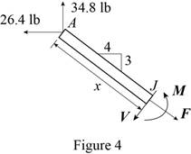
Sketch the free body diagram for the
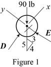
Write the equation of the axial force exerted at the axial point of the pipe from x direction.
Here, the pipe is supported by a small frame on the member is
Write the equation of the axial force exerted at the point on the pipe from y direction.
Here, the force exerted on the pipe at y direction in equilibrium condition is
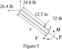
Sketch the free body diagram for the frame as shown in the Figure 2.
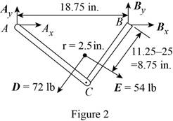
Write the equation of the moment of couple formed in the bending moment of the frame at the point
Here, the force exerted on the member of the pipe at point
Write the equation of the axial force exerted at the point on the pipe from y direction (Refer fig 2).
Here, the force exerted on the member of the pipe on frame at the point
Write the equation of the axial force exerted at the axial point of the pipe from x direction (Refer fig 2).
Sketch the free body diagram for the member of the frame from the point
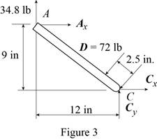
Write the equation of the moment of couple formed in the bending moment supported at the point
Here, the distance of the frame
Sketch the free body diagram for the member of the frame from the portion
Write the equation of the moment of couple formed in the bending moment supported at the point
Sketch the free body diagram for the member of the frame from the portion
Write the equation of the moment of couple formed in the bending moment supported at the point
Conclusion:
Substitute
Substitute
Substitute
Substitute
Substitute
Substitute
Substitute
Substitute
Substitute
Substitute
Therefore, the magnitude of the bending moment of couple exerted at the point
Want to see more full solutions like this?
Chapter 7 Solutions
Connect 2 Semester Access Card for Vector Mechanics for Engineers: Statics and Dynamics


- Two small channel sections DF and EH have been welded to the uniform beam AB of weight W = 3 kN to form the rigid structural member shown. This member is being lifted by two cables attached at D and E . Knowing that 0= 30° and neglecting the weight of the channel sections, (a) draw the shear and bending-moment diagrams for beam AB, (b) determine the maximum absolute values of the shear and bending moment in the beam.arrow_forwardThe center span of the Verrazano-Narrows Bridge consists of two uniform roadways suspended from four cables. The design of the bridge allows for the effect of extreme temperature changes that cause the sag of the center span to vary from hw= 386 ft in winter to hs= 394 ft in summer. Knowing that the span is L = 4260 ft, determine the change in length of the cables due to extreme temperature changes.arrow_forwardA half section of pipe rests on a frictionless horizontal surface as shown. If the half section of pipe has a mass of 9 kg and a diameter of 300 mm, determine the bending moment at point J when 0=90°.arrow_forward
- Determine the sag of a 30-ft chain that is attached to two points at the same elevation that are 20 ft apart.arrow_forwardA uniform beam is to be picked up by crane cables attached at A and B. Determine the distance afrom the ends of the beam to the points where the cables should be attached if the maximum absolute value of the bending moment in the beam is to be as small as possible. (Hint: Draw the bending-moment diagram in terms of a, L, and the weight per unit length w , and then equate the absolute values of the largest positive and negative bending moments obtained.)arrow_forwardSolve Prob. 7.43 knowing that P= 3wa.(Reference to Problem 7.43):Assuming the upward reaction of the ground on beam AB to be uniformly distributed and knowing that P= wa, (a) draw the shear and bending-moment diagrams, (b) determine the maximum absolute values of the shear and bending moment.arrow_forward
- Knowing the vertical reaction at the roller support at C of the beam shown is 12.5 kN upward, determine the requested algebraic expressions for shear and moment (in terms of the variable x), using the proper sign conventions established for drawing the shear and bending moment diagrams. (a) The shear and moment equations (in terms of the variable x) for the left region of the beam between points A and B, using the F.B.D. of the left-side of your considered cut section (b) The shear and moment equations (in terms of the variable x) for the right region of the beam between points B and C using the F.B.D. of the right-side of your considered cut section.please show all steps and FBD.arrow_forwardKnowing that P=Q= 480 N, determine (a) the distance a for which the absolute value of the bending moment in the beam is as small as possible, (b) the corresponding maximum normal stress due to bending.arrow_forwardProvided that the bending formation of a straight member is small and within elastic range, and neutral axis is denoted as z axis as shown below, the normal stress, σx ( fb in textbook) developed by bending moment on cross section will not vary along z direction. True Falsearrow_forward
- The uniform 10 kg rod AB is supported by a ball and socket joint at A and by the cord CG that is attached to the midpoint G of the rod. Knowing that the rod leans against a frictionless vertical wall at B and that the tension in the cord CG, TCG=52.1 N, determine the following, Which of the following best approximates the moment of the weight of the structure about A? Choices: (7.36i + 29.4k) N-m(7.36i + 29.4j) N-m(29.4i + 7.36k) N-m(29.4i + 7.36j) N-marrow_forwardA composite beam is constructed by bolting four plates to four 60 × 60 × 12-mm angles as shown. The bolts are equally spaced along the beam, and the beam supports a vertical load. As proved in mechanics of materials, the shearing forces exerted on the bolts at A and B are proportional to the first moments with respect to the centroidal x axis of the red shaded areas shown, respectively, in parts a and b of the figure. Knowing that the force exerted on the bolt at A is 280 N, determine the force exerted on the bolt at B.arrow_forwardThree bars, two made of aluminum and one made of steel, support a rigid block. An object of weight W is dropped vertically from a distance h above the rigid block. Both steel and aluminum bars have cross-sectional area of 50 mm2 and length of 0.5 m. The elastic moduli for the aluminum and steel are 76 GPa and 184 GPa, respectively. a) If W=1000N and h=0.1m, determine whether the three bars are still safe to perform. b) If h=0.2m, determine the maximum weight that can be dropped without causing failure to the barsarrow_forward
 Elements Of ElectromagneticsMechanical EngineeringISBN:9780190698614Author:Sadiku, Matthew N. O.Publisher:Oxford University Press
 Mechanics of Materials (10th Edition)Mechanical EngineeringISBN:9780134319650Author:Russell C. HibbelerPublisher:PEARSON
 Thermodynamics: An Engineering ApproachMechanical EngineeringISBN:9781259822674Author:Yunus A. Cengel Dr., Michael A. BolesPublisher:McGraw-Hill Education
 Control Systems EngineeringMechanical EngineeringISBN:9781118170519Author:Norman S. NisePublisher:WILEY
 Mechanics of Materials (MindTap Course List)Mechanical EngineeringISBN:9781337093347Author:Barry J. Goodno, James M. GerePublisher:Cengage Learning
 Engineering Mechanics: StaticsMechanical EngineeringISBN:9781118807330Author:James L. Meriam, L. G. Kraige, J. N. BoltonPublisher:WILEY