Concept explainers
Videos
For the frame of Prob. 7.17, determine the magnitude and location of the maximum bending moment in member BC.
The bending moment of the couple exerted at the point
Answer to Problem 7.18P
The magnitude of the bending moment of couple exerted at the point
Explanation of Solution
Sketch the free body diagram for the pipe as shown in the Figure 1.
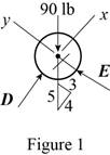
Write the equation of the axial force exerted at the axial point of the pipe from x direction.
Here, the pipe is supported by a small frame on the member is
Write the equation of the axial force exerted at the point on the pipe from y direction.
Here, the force exerted on the pipe at y direction in equilibrium condition is
Sketch the free body diagram for the frame as shown in the Figure 2.
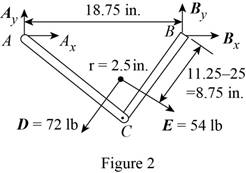
Write the equation of the moment of couple formed in the bending moment of the frame at the point
Here, the force exerted on the member of the pipe at point
Write the equation of the axial force exerted at the point on the pipe from y direction (Refer fig 2).
Here, the force exerted on the member of the pipe on frame at the point
Write the equation of the axial force exerted at the axial point of the pipe from x direction (Refer fig 2).
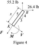
Sketch the free body diagram for the member of the frame from the point
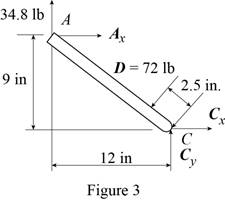
Write the equation of the moment of couple formed in the bending moment supported at the point
Here, the distance of the frame
Sketch the free body diagram for the member of the frame from the portion
Write the equation of the moment of couple formed in the bending moment supported at the point
Sketch the free body diagram for the member of the frame from the portion
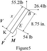
Write the equation of the moment of couple formed in the bending moment supported at the point
Conclusion:
Substitute
Substitute
Substitute
Substitute
Substitute
Substitute
Substitute
Substitute
Substitute
Substitute
Therefore, the magnitude of the bending moment of couple exerted at the point
Want to see more full solutions like this?
Chapter 7 Solutions
Connect 2 Semester Access Card for Vector Mechanics for Engineers: Statics and Dynamics


- A 14 ft long beam ABC supports a frictionless pulley with 12 in radius at point B, located 10 ft from the left end. The cable DC supports 150 lb weight W as shown. Determine and direction of the reaction at the roller at C. Determine the magnitude and direction of the reaction at pin A.arrow_forwardFor the beam shown, determine (a) the magnitude P of the two upward forces for which the maximum absolute value of the bending moment in the beam is as small as possible, (b) the corresponding value of |M| max.arrow_forwardKnowing that the radius of each pulley is 200 mm and neglecting friction, determine the internal forces at point J of the frame shown.arrow_forward
- A force of 90 N is applied on a lever AB as shown in the figure. Knowing that the lever is 225 mm long and that the moment of force in relation to point B is 13.5 N.m clockwise, determine the value of α.arrow_forwardTwo small channel sections DF and EH have been welded to the uniform beam AB of weight W = 3 kN to form the rigid structural member shown. This member is being lifted by two cables attached at D and E . Knowing that 0= 30° and neglecting the weight of the channel sections, (a) draw the shear and bending-moment diagrams for beam AB, (b) determine the maximum absolute values of the shear and bending moment in the beam.arrow_forwardDetermine (a) the equations of the shear and bending-moment curves for the beam and loading shown, (b) the maximum absolute value of the bending moment in the beamarrow_forward
- A composite beam is constructed by bolting four plates to four 60x60 x 12-mm angles as shown. The bolts are equally spaced along the beam, and the beam supports a vertical load. As proved in mechanics of materials, the shearing forces exerted on the bolts at A and B are proportional to the first moments with respect to the centroidal x axis of the red shaded areas shown, respectively, in parts a and b of the figure. Knowing that the force exerted on the bolt at A is 280 N, determine the force exerted on the bolt at B.arrow_forwardShow that, when a rigid body rotates about a fixed axis through O perpendicular to the body, the system of the momenta of its particles is equivalent to a single vector of magnitude mrw, perpendicular to the line OG, and applied to a point P on this line, called the center of percussion, at a distance GP=k2/r from the mass center of the body.arrow_forwardDetermine (a) the equations of the shear and bending moment curves for the beam and loading shown, (b) the maximum absolute value of the bending moment in the beam.arrow_forward
- The rectangular tube shown is extruded from an aluminum alloy for which σY= 40 ksi, σU= 60 ksi, and E= 10.6 * 106 psi. Neglecting the effect of fillets, determine (a) the bending moment M for which the factor of safety will be 3.00 and (b) the corresponding radius of curvature of the tubearrow_forwardA weightlifting bar is loaded symmetrically in A and D (P = 1500N of each side). The weightlifter's hands are located at B and C, 0.45 m from A and D. Determine the maximum bending moment in the bar ABCD and the minimum diameter d of the bar knowing that the constraint admissible for the material of the bar is 200MPa.arrow_forwardA steam pipe weighing 45 lb/ft that passes between two buildings 40 ft apart is supported by a system of cables as shown. Assuming that the weight of the cable system is equivalent to a uniformly distributed loading of 5 lb/ft, determine (a) the location of the lowest point C of the cable, (b) the maximum tension in the cable.arrow_forward
 Elements Of ElectromagneticsMechanical EngineeringISBN:9780190698614Author:Sadiku, Matthew N. O.Publisher:Oxford University Press
 Mechanics of Materials (10th Edition)Mechanical EngineeringISBN:9780134319650Author:Russell C. HibbelerPublisher:PEARSON
 Thermodynamics: An Engineering ApproachMechanical EngineeringISBN:9781259822674Author:Yunus A. Cengel Dr., Michael A. BolesPublisher:McGraw-Hill Education
 Control Systems EngineeringMechanical EngineeringISBN:9781118170519Author:Norman S. NisePublisher:WILEY
 Mechanics of Materials (MindTap Course List)Mechanical EngineeringISBN:9781337093347Author:Barry J. Goodno, James M. GerePublisher:Cengage Learning
 Engineering Mechanics: StaticsMechanical EngineeringISBN:9781118807330Author:James L. Meriam, L. G. Kraige, J. N. BoltonPublisher:WILEY