
Concept explainers
Videos
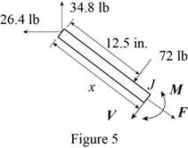
The bending moment of the couple exerted at the point
Answer to Problem 7.17P
The magnitude of the bending moment of couple exerted at the point
Explanation of Solution
Sketch the free body diagram for the
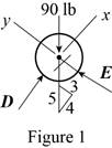
Write the equation of the axial force exerted at the axial point of the pipe from x direction.
Here, the pipe is supported by a small frame on the member is
Write the equation of the axial force exerted at the point on the pipe from y direction.
Here, the force exerted on the pipe at y direction in equilibrium condition is
Sketch the free body diagram for the frame as shown in the Figure 2.
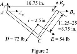
Write the equation of the moment of couple formed in the bending moment of the frame at the point
Here, the force exerted on the member of the pipe at point
Write the equation of the axial force exerted at the point on the pipe from y direction (Refer fig 2).
Here, the force exerted on the member of the pipe on frame at the point
Write the equation of the axial force exerted at the axial point of the pipe from x direction (Refer fig 2).
Sketch the free body diagram for the member of the frame from the point
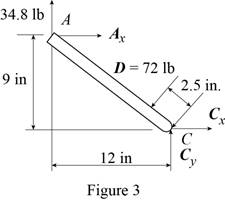
Write the equation of the moment of couple formed in the bending moment supported at the point
Here, the distance of the frame
Sketch the free body diagram for the member of the frame from the portion
Write the equation of the moment of couple formed in the bending moment supported at the point
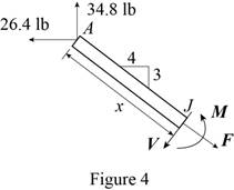
Sketch the free body diagram for the member of the frame from the portion
Write the equation of the moment of couple formed in the bending moment supported at the point
Conclusion:
Substitute
Substitute
Substitute
Substitute
Substitute
Substitute
Substitute
Substitute
Substitute
Substitute
Therefore, the magnitude of the bending moment of couple exerted at the point
Want to see more full solutions like this?
Chapter 7 Solutions
VECTOR MECH...,STAT.+DYNA.(LL)-W/ACCESS


- A semicircular rod of weight W and uniform cross section is supported as shown. Determine the bending moment at point J w hen 0=60°.Fig. P7.23arrow_forwardA cable AB of span L and a simple beam A'B' of the same span are subjected to identical vertical loadings as shown. Show that the magnitude of the bending moment at a point C' in the beam is equal to the product T0h, where T0 is the magnitude of the horizontal component of the tension force in the cable and h is the vertical distance between point C and the chord joining the points of support A and B.arrow_forwardKnowing that the radius of each pulley is 200 mm and neglecting friction. determine the internal forces at point K of the frame shown.Fig. P7.18arrow_forward
- Two live loads of 7 KN and 9 KN separated 5 m apart, are to cross a simple beam. Also, a uniform live load of 6 KN/m, 6 m long, is expected to cross the same beam. The simple supports are marked A and B and a point C is located 4 m from A. Determine: (a) the maximum moment at C due to the two concentrated live loads if the length of the beam is (a.1) 8.4 m; (a.2) 10 m. (b) The maximum moment at C due to the uniform live load if the length of the beam is (b.1) 8.4 m; (b.2) 10 m. (c) The maximum moment in the beam due to the combined effects of the two concentrated live loads and the uniform live loads if the length of the beam is (c.1) 8.4 m; (c.2) 10 m. part (c), I am asking for the ABSOLUTE maximum moment in the beam due to the combined effects of the two live loads and the uniform live load. Please be guided and informed accordingly. Good luck!arrow_forward6.43-6.56 Construct the shear force and bending moment diagrams for the beam shown by the area method. Neglect the weight of the beam. 100 lb 120 lb/ft 120 lb/ft В А D 2 ft – 2 ft 2 ft – Fig. P6.47arrow_forward6.70 A uniform cable weighing 15 N/m is suspended from points A and B. The force in the cable at B is known to be 500 N. Using the result of Prob. 6.69, calculate (a) the force in the cable at A; and (b) the span L. B 8 m 4 m Fig. P6.70arrow_forward
- Solve Prob. 7.43 knowing that P= 3wa.(Reference to Problem 7.43):Assuming the upward reaction of the ground on beam AB to be uniformly distributed and knowing that P= wa, (a) draw the shear and bending-moment diagrams, (b) determine the maximum absolute values of the shear and bending moment.arrow_forward-2 m -2 m – 4.5 kN 1.4 kN E 2.8 kN Do G 0.5 m F 1 kN I kN B 3 m I kN. I kN A |C I 1 m '1m 1 m 1 m Fig. P6.15 and P6.16 6.16 For the Gambrel roof truss shown, determine the force in members CG and CI and in each of the members located to the right of the centerline of the truss. State whether each member is in tension or compression.arrow_forward(b) The gudgeon pin is used to connect the piston and the connecting rod. Show from first principles that the maximum bending moment acting on the gudgeon pin is given by: PL M = 8 where P is the maximum gas load and L is the length of the pinarrow_forward
- The uniform 10 kg rod AB is supported by a ball and socket joint at A and by the cord CG that is attached to the midpoint G of the rod. Knowing that the rod leans against a frictionless vertical wall at B and that the tension in the cord CG, TCG=52.1 N, determine the following, Which of the following best approximates the moment of the weight of the structure about A? Choices: (7.36i + 29.4k) N-m(7.36i + 29.4j) N-m(29.4i + 7.36k) N-m(29.4i + 7.36j) N-marrow_forwardProblem 7. The 30-mm diameter shaft is subjected to the vertical and horizontal loadings of two pulleys as shown. It is supported on two journal bearings at A and B which offer no resistance to axial loading. Furthermore, the coupling to the motor at C can be assumed not to offer any support to the shaft. The shaft is subjected to both Mz and My internal bending moment components. (a) Draw a bending moment diagram for each component. (b) Since all axes through the circle's center for circular shaft are principal axis, then the resultant M = √M²+ M² can be used to determine the y maximum bending stress. Determine the location and magnitude of maximum normal stress due to bending developed in the shaft. X 150 N 1 m 2 150 N 1 m E 60 mm 1 m 100 mm 1 m 400 N 400 Narrow_forwardA 20-m length of wire having a mass per unit length of 0.2 kg/m is attached to a fixed support at A and to a collar at B . Knowing that the magnitude of the horizontal force applied to the collar is P= 20 N, determine (a) the sag h, (b) the span L.arrow_forward
 Elements Of ElectromagneticsMechanical EngineeringISBN:9780190698614Author:Sadiku, Matthew N. O.Publisher:Oxford University Press
 Mechanics of Materials (10th Edition)Mechanical EngineeringISBN:9780134319650Author:Russell C. HibbelerPublisher:PEARSON
 Thermodynamics: An Engineering ApproachMechanical EngineeringISBN:9781259822674Author:Yunus A. Cengel Dr., Michael A. BolesPublisher:McGraw-Hill Education
 Control Systems EngineeringMechanical EngineeringISBN:9781118170519Author:Norman S. NisePublisher:WILEY
 Mechanics of Materials (MindTap Course List)Mechanical EngineeringISBN:9781337093347Author:Barry J. Goodno, James M. GerePublisher:Cengage Learning
 Engineering Mechanics: StaticsMechanical EngineeringISBN:9781118807330Author:James L. Meriam, L. G. Kraige, J. N. BoltonPublisher:WILEY