
Concept explainers
Videos
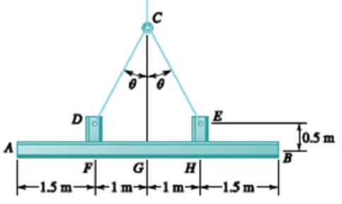
For the structural member of Prob. 7.53, determine (a) the angle θ for which the maximum absolute value of the bending moment in beam AB is as small as possible, (b) the corresponding value of |M|max. (Hint: Draw the bending-moment diagram and then equate the absolute values of the largest positive and negative bending moments obtained.)
PROBLEM 7.53 Two small channel sections DF and EH have been welded to the uniform beam AB of weight W = 3 kN to form the rigid structural member shown. This member is being lifted by two cables attached at D and E. Knowing that θ = 30° and neglecting the weight of the channel sections, (a) draw the shear and bending-moment diagrams for beam AB, (b) determine the maximum absolute values of the shear and bending moment in the beam.
Want to see the full answer?
Check out a sample textbook solution
Chapter 7 Solutions
Vector Mechanics for Engineers: Statics and Dynamics


- Determine (a) the distance a for which the maximum absolute value of the bending moment in the beam is as small as possible, (b) the corresponding maximum normal stress due to bending.arrow_forwardDraw the shearing-force and bending-moment diagrams for the following beams: A cantilever of length 20 m carrying a load of 10 kN at a distance of 15 m from the supported end. A cantilever of length 20 m carrying a load of 10 kN uniformly distributed over the inner 15 m of its length. A cantilever of length 12 m carrying a load of 8 kN, applied 5 m from the supported end, and a load of 2kN/m over its whole length.arrow_forwardProblem 03: Draw the shear and bending-moment diagrams for the beam and loading shown, and determine the maximum absolute value (a) of the shear, (b) of the bending moment.arrow_forward
- For the beam and loading shown, determine the equations of the shear and bending-moment curves and the maximum absolute value of the bending moment in the beam, knowing that (a) k= 1, (b) k= 0.5.arrow_forwardProvided that the bending formation of a straight member is small and within elastic range, and neutral axis is denoted as z axis as shown below, the normal stress, σx ( fb in textbook) developed by bending moment on cross section will not vary along z direction. True Falsearrow_forwardKnowing that P=Q= 480 N, determine (a) the distance a for which the absolute value of the bending moment in the beam is as small as possible, (b) the corresponding maximum normal stress due to bending.arrow_forward
- Knowing the vertical reaction at the roller support at C of the beam shown is 12.5 kN upward, determine the requested algebraic expressions for shear and moment (in terms of the variable x), using the proper sign conventions established for drawing the shear and bending moment diagrams. (a) The shear and moment equations (in terms of the variable x) for the left region of the beam between points A and B, using the F.B.D. of the left-side of your considered cut section (b) The shear and moment equations (in terms of the variable x) for the right region of the beam between points B and C using the F.B.D. of the right-side of your considered cut section.please show all steps and FBD.arrow_forwardSolve Prob. 7.43 knowing that P= 3wa.(Reference to Problem 7.43):Assuming the upward reaction of the ground on beam AB to be uniformly distributed and knowing that P= wa, (a) draw the shear and bending-moment diagrams, (b) determine the maximum absolute values of the shear and bending moment.arrow_forwardA 12-m simply supported overhang beam is supported at x = 0 and x = 10m. The overhanging portion is from x = 10m to x = 12m (the overhang portion is 2m). Two equal wheel loads of 20kN each, separated by 2m roll as a unit across the 12-m span. Determine the maximum shear developed in the span.arrow_forward
- Determine the shape of a fully stressed, simply supported beam that supportsa concentrated force at its center, Fig. 11–11a. The beam has a rectangularcross section of constant width b, and the allowable stress is sallow.arrow_forwardA solid beam supported on bearings 15 ft apart, has a cross-section of 1/2 in deep and 3/8 in wide. Determine the bending stress in the beam assuming that a load of 10 lbis applied gradually at the center of the beam length.arrow_forwardA timber beam AB of length L and rectangular cross section carries a single concentrated load P at its midpoint C. (a) Show that the ratio Tm/ m of the maximum values of the shearing and normal stresses in the beam is equal to h/2L, where h and L are, respectively, the depth and the length of the beam. (b) Determine the depth h and the width b of the beam, knowing that L = 2 m, P = 40 kN, 7m = 960 kPa, and om = 12 MPa.arrow_forward
 Elements Of ElectromagneticsMechanical EngineeringISBN:9780190698614Author:Sadiku, Matthew N. O.Publisher:Oxford University Press
 Mechanics of Materials (10th Edition)Mechanical EngineeringISBN:9780134319650Author:Russell C. HibbelerPublisher:PEARSON
 Thermodynamics: An Engineering ApproachMechanical EngineeringISBN:9781259822674Author:Yunus A. Cengel Dr., Michael A. BolesPublisher:McGraw-Hill Education
 Control Systems EngineeringMechanical EngineeringISBN:9781118170519Author:Norman S. NisePublisher:WILEY
 Mechanics of Materials (MindTap Course List)Mechanical EngineeringISBN:9781337093347Author:Barry J. Goodno, James M. GerePublisher:Cengage Learning
 Engineering Mechanics: StaticsMechanical EngineeringISBN:9781118807330Author:James L. Meriam, L. G. Kraige, J. N. BoltonPublisher:WILEY