
Concept explainers
Videos
Knowing that P = Q = 150 lb, determine (a) the distance a for which the maximum absolute value of the bending moment in beam AB is as small as possible, (b) the corresponding value of |M|max. (See the hint for Prob. 7.55.)
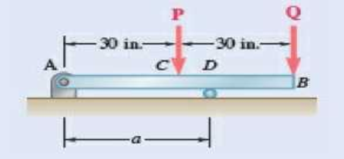
Fig. P7.60
(a)
The distance a from the ends of the beam to the points where the cables should be attached if the maximum absolute value of the bending moment in the beam AB is the smallest.
Answer to Problem 7.60P
The distance a from the ends of the beam to the points where the cables should be attached if the maximum absolute value of the bending moment in the beam AB is the smallest is
Explanation of Solution
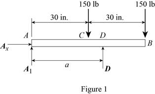
Refer Figures 1.
Write an expression to calculate the counter clockwise moment at point A.
Here,
Write an expression to calculate the counter clockwise moment at point A.
Here,
Write an expression to calculate the counter clockwise moment at point A.
Here,
Conclusion:
Refer Figure 1:
Calculate the moment about point A.
Here,
Rearrange the equation to calculate the D.
Substitute
Refer figure 2.
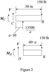
Calculate the moment about point C.
Rearrange the equation to calculate the
Substitute
Refer figure 2.
Calculate the moment about point D.
Rearrange the equation to calculate the
Substitute
The magnitude of the maximum moment is equal to the magnitude of the minimum moment.
Substitute (I) and (II) in above equation to find a.
Rearrange the equation to find a.
Thus, the distance a from the ends of the beam to the points where the cables should be attached if the maximum absolute value of the bending moment in the beam AB is the smallest is
(b)
The value of
Answer to Problem 7.60P
The value of
Explanation of Solution
Refer figure 4.
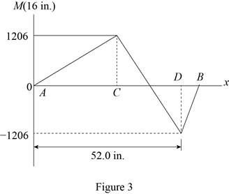
The magnitude of the maximum moment is equal to the magnitude of the minimum moment.
Conclusion:
Substitute
Thus, the value of
Want to see more full solutions like this?
Chapter 7 Solutions
Vector Mechanics for Engineers: Statics and Dynamics


- Knowing that P=Q= 480 N, determine (a) the distance a for which the absolute value of the bending moment in the beam is as small as possible, (b) the corresponding maximum normal stress due to bending.arrow_forwardA) The four cross sections shown have different characteristics when subjected to a vertical shear force. Which of the four geometries shown has the largest value for the moment of the area, Q, about the neutral axis? B) Which of the four geometries shown has the smallest value for its moment of inertia about the x axis? C) Given that all four geometries are subjected to the same vertical shear force V, which of the four has the smallest value for the maximum shear stress?arrow_forwardProvided that the bending formation of a straight member is small and within elastic range, and neutral axis is denoted as z axis as shown below, the normal stress, σx ( fb in textbook) developed by bending moment on cross section will not vary along z direction. True Falsearrow_forward
- Determine the sag of a 30-ft chain that is attached to two points at the same elevation that are 20 ft apart.arrow_forwardSolve Prob. 7.43 knowing that P= 3wa.(Reference to Problem 7.43):Assuming the upward reaction of the ground on beam AB to be uniformly distributed and knowing that P= wa, (a) draw the shear and bending-moment diagrams, (b) determine the maximum absolute values of the shear and bending moment.arrow_forwardTwo small channel sections DF and EH have been welded to the uniform beam AB of weight W = 3 kN to form the rigid structural member shown. This member is being lifted by two cables attached at D and E . Knowing that 0= 30° and neglecting the weight of the channel sections, (a) draw the shear and bending-moment diagrams for beam AB, (b) determine the maximum absolute values of the shear and bending moment in the beam.arrow_forward
- A timber beam AB of length L and rectangular cross section carries a single concentrated load P at its midpoint C. (a) Show that the ratio Tm/ m of the maximum values of the shearing and normal stresses in the beam is equal to h/2L, where h and L are, respectively, the depth and the length of the beam. (b) Determine the depth h and the width b of the beam, knowing that L = 2 m, P = 40 kN, 7m = 960 kPa, and om = 12 MPa.arrow_forwardDetermine (a) the distance a for which the maximum absolute value of the bending moment in the beam is as small as possible, (b) the corresponding maximum normal stress due to bending.arrow_forwardDraw the shearing-force and bending-moment diagrams for the following beams: A cantilever of length 20 m carrying a load of 10 kN at a distance of 15 m from the supported end. A cantilever of length 20 m carrying a load of 10 kN uniformly distributed over the inner 15 m of its length. A cantilever of length 12 m carrying a load of 8 kN, applied 5 m from the supported end, and a load of 2kN/m over its whole length.arrow_forward
- The rectangular tube shown is extruded from an aluminum alloy for which σY= 40 ksi, σU= 60 ksi, and E= 10.6 * 106 psi. Neglecting the effect of fillets, determine (a) the bending moment M for which the factor of safety will be 3.00 and (b) the corresponding radius of curvature of the tubearrow_forwardA semicircular rod of weight W and uniform cross section is supported as shown. Determine the bending moment at point J w hen 0=60°.Fig. P7.23arrow_forwardKnowing the vertical reaction at the roller support at C of the beam shown is 12.5 kN upward, determine the requested algebraic expressions for shear and moment (in terms of the variable x), using the proper sign conventions established for drawing the shear and bending moment diagrams. (a) The shear and moment equations (in terms of the variable x) for the left region of the beam between points A and B, using the F.B.D. of the left-side of your considered cut section (b) The shear and moment equations (in terms of the variable x) for the right region of the beam between points B and C using the F.B.D. of the right-side of your considered cut section.please show all steps and FBD.arrow_forward
 Elements Of ElectromagneticsMechanical EngineeringISBN:9780190698614Author:Sadiku, Matthew N. O.Publisher:Oxford University Press
 Mechanics of Materials (10th Edition)Mechanical EngineeringISBN:9780134319650Author:Russell C. HibbelerPublisher:PEARSON
 Thermodynamics: An Engineering ApproachMechanical EngineeringISBN:9781259822674Author:Yunus A. Cengel Dr., Michael A. BolesPublisher:McGraw-Hill Education
 Control Systems EngineeringMechanical EngineeringISBN:9781118170519Author:Norman S. NisePublisher:WILEY
 Mechanics of Materials (MindTap Course List)Mechanical EngineeringISBN:9781337093347Author:Barry J. Goodno, James M. GerePublisher:Cengage Learning
 Engineering Mechanics: StaticsMechanical EngineeringISBN:9781118807330Author:James L. Meriam, L. G. Kraige, J. N. BoltonPublisher:WILEY