
Control Systems Engineering
7th Edition
ISBN: 9781118170519
Author: Norman S. Nise
Publisher: WILEY
expand_more
expand_more
format_list_bulleted
Concept explainers
Videos
Textbook Question
Chapter 8, Problem 2P
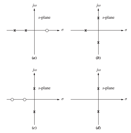
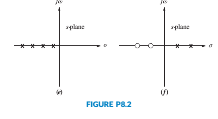
Sketch the general shape of the root locus for each of the open-loop pole-zero plots shown in Figure P8.2. [Section: 8.4]
Expert Solution & Answer
Want to see the full answer?
Check out a sample textbook solution
Students have asked these similar questions
For the given close-loop system transfer function, determine its stability using Routh-Hurwitz Test for Stability.1. What is the stability of the system? (Stable, Unstable, Marginally Stable)
1. Give an example of open loop and closed loop system (one example each). Also state the input, control system, feedback and output parameter.
Example.
1. Open Loop - Water Heater:
Input - Water Temperature (Cold)
System - Heating Element
Output - Water Temperature (Hot)
2. Closed Loop - Air-conditioning System
Input - Desired Room Temperature
Control - Motor controller/Compressor/ACU
Feedback - Temperature Sensing
Output - Room Temperature
a)is the aircraft stable about the equilibrium represented by the transfer function?
b) Using proportional feedback,what is the range of acceptable gains for the closed loop systen to be stable?
c) Design a feedback control system that allows the pilot to command a pitch angle with overshoot less than or equal to 4.15% and a natural frequency of greater than or equal to 0.99 rad/s
d) Design a feedback control system that allows the pilot to command a pitch angle with the same overshoot and a natural frequency of one half the system in part c.
Chapter 8 Solutions
Control Systems Engineering
Ch. 8 - Prob. 1RQCh. 8 - Prob. 2RQCh. 8 - Prob. 3RQCh. 8 - Prob. 4RQCh. 8 - Prob. 5RQCh. 8 - What are two ways to find where the root locus...Ch. 8 - Prob. 7RQCh. 8 - Prob. 8RQCh. 8 - Prob. 9RQCh. 8 - How would you determine whether or not a root...
Ch. 8 - Prob. 11RQCh. 8 - Prob. 12RQCh. 8 - Prob. 13RQCh. 8 - Prob. 1PCh. 8 - Sketch the general shape of the root locus for...Ch. 8 - Prob. 3PCh. 8 - Let Gs=Ks+23s2s+6 in Figure P8.3. [Section: 8.5]...Ch. 8 - Let Gs=Ks+12s2+2s+2 with K0 in Figure P8.3....Ch. 8 - For the open-loop pole-zero plot shown in Figure...Ch. 8 - Prob. 7PCh. 8 - Prob. 8PCh. 8 - Figure P8.5 shows open-loop poles and zeros. There...Ch. 8 - Prob. 10PCh. 8 - Prob. 11PCh. 8 - Prob. 12PCh. 8 - Prob. 13PCh. 8 - Sketch the root locus and find the range of K for...Ch. 8 - For the unity feedback system of Figure P8.3,...Ch. 8 - Prob. 16PCh. 8 - Prob. 17PCh. 8 - Given the root locus shown in Figure P8.7,...Ch. 8 - Prob. 19PCh. 8 - For the unity feedback system of Figure P8.3,...Ch. 8 - Prob. 21PCh. 8 - Prob. 22PCh. 8 - Prob. 23PCh. 8 - Prob. 24PCh. 8 - Prob. 25PCh. 8 - Prob. 26PCh. 8 - Prob. 28PCh. 8 - Prob. 29PCh. 8 - Prob. 30PCh. 8 - Prob. 31PCh. 8 - For the unity feedback system shown in Figure 8.3,...Ch. 8 - Prob. 34PCh. 8 - Prob. 35PCh. 8 - Prob. 37PCh. 8 - Prob. 38PCh. 8 - Prob. 39PCh. 8 - Prob. 41PCh. 8 - Prob. 42PCh. 8 - Prob. 45PCh. 8 - Repeat Problem 3 but sketch your root loci for...Ch. 8 - Prob. 47PCh. 8 - Prob. 49PCh. 8 - Prob. 50PCh. 8 - Prob. 51PCh. 8 - Prob. 52PCh. 8 - Prob. 53PCh. 8 - Prob. 55PCh. 8 - Prob. 57PCh. 8 - Prob. 58PCh. 8 - Prob. 59PCh. 8 - Wind turbines, such as the one shown in Figure...Ch. 8 - Prob. 62PCh. 8 - Prob. 67PCh. 8 - Prob. 68PCh. 8 - Prob. 70PCh. 8 - Prob. 72P
Knowledge Booster


Learn more about
Need a deep-dive on the concept behind this application? Look no further. Learn more about this topic, mechanical-engineering and related others by exploring similar questions and additional content below.Similar questions
- Q.1 - The open loop transfer function for a unity - feedback systemis G(s)= XL‘ 7xs and r(t)=3t determine steady state error.If it is desired to reduce this existing error by 7% fined new value of gain of the system.arrow_forwardThe close loop system block diagram is given below .Find the transfer function of the given system.arrow_forward(Figure 1 One Wheel Model), Part1-(Derive equation of motion for a given system and obtain transfer function and state space representation.) , part2-(Draw closed-loop diagram for full-state- feedback controller.) , part3- (Select proper coefficient (u=-Kx) satisfying that .) part4- (Simulate the closed-loop system and show the response of it.) Note: Tahe Reference signal as With f = 0.1 Hz. !!!!!!!!! Please solve these steps, at least the first step which is writing the equations of motion of the system and the second step which is drawing closed loop diagram for Full state feedback controller.!!!!arrow_forward
- root locus electrical engineering Don't overthink and reject. Complete the solution as per the given transfer function. No need of quadratic equation just simplify for the exact given transfer function.arrow_forwardReduce the block diagram shown in Figure below to a single transfer function, T(s) = C(s)/R(s) Use the block diagram reduction method.arrow_forwardA vibrating spring-mass system has the feedback control system shown in Fig Q3 below. (figure attached as image ACT)If K = 12.25 determine:6.1 the transfer function ; (3)6.2 the characteristic equation with a impulse input; (1)6.3 the un-damped natural frequency of the system; (2)6.4 the damping ratio; (2)6.5 the damped natural frequency; (2)6.6 the maximum percentage overshoot; (2)6.7 the peak time; (1)6.8 the settling time for the response within 2%. (2)arrow_forward
- A Block diagram of a feedback control system is shown in Figure Q3. Using the Block Diagram Reduction Method, solve for the output Y(s) when:(i) Input D(s) = 0,(ii) Input R(s) = 0,(iii) Input R(s) and D(s) are both applied (i.e., R(s) ≠ 0 , D(s) ≠ 0).arrow_forwardA system has the following characteristic equation: s+ s+ 3s+ 2s + 2 = 0 Using the Routh-Hurwitz method, checka. How many roots are to the right of the imaginary axis?b. Is the system stable?.arrow_forwardexplain please. Which type(s) of systems will oscillate in response to a step function?arrow_forward
- TIME DOMAIN MODELING AND RESPONSE FOR CONTROL SYSTEMSarrow_forwardWrite the transfer function of figure 1.3 for the given values, add the BODE diagram andpoles-zeros graph.Use the keyboard, do not write by handarrow_forwardObtain the state space model of the system shown below. Use equations for control theory state space modeling.arrow_forward
arrow_back_ios
SEE MORE QUESTIONS
arrow_forward_ios
Recommended textbooks for you
 Principles of Heat Transfer (Activate Learning wi...Mechanical EngineeringISBN:9781305387102Author:Kreith, Frank; Manglik, Raj M.Publisher:Cengage Learning
Principles of Heat Transfer (Activate Learning wi...
Mechanical Engineering
ISBN:9781305387102
Author:Kreith, Frank; Manglik, Raj M.
Publisher:Cengage Learning
Introduction to Undamped Free Vibration of SDOF (1/2) - Structural Dynamics; Author: structurefree;https://www.youtube.com/watch?v=BkgzEdDlU78;License: Standard Youtube License