
Control Systems Engineering
7th Edition
ISBN: 9781118170519
Author: Norman S. Nise
Publisher: WILEY
expand_more
expand_more
format_list_bulleted
Concept explainers
Videos
Textbook Question
Chapter 8, Problem 9P
Figure P8.5 shows open-loop poles and zeros. There are two possibilities for the sketch of the root locus. Sketch each of the two possibilities. Be aware that only one can be the real locus for specific open-loop pole and zero values. [Section: 8.4] 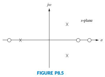
Expert Solution & Answer

Trending nowThis is a popular solution!

Students have asked these similar questions
For the given close-loop system transfer function, determine its stability using Routh-Hurwitz Test for Stability.1. What is the stability of the system? (Stable, Unstable, Marginally Stable)
Given the system equipped with unitary feedback, whose direct branch transfer function is:
Design a PID controller with one of the Ziegler-Nichols methods.
A stock-flow system models the level of water in a lake. Near a certain equilibrium point, there are three feedback loops: an amplifying feedback loop with strength of +0.55 per month, a stabilizing feedback loop with strength of -0.09 per month, and an amplifying feedback loop with strength of +0.79 per month.
Calculate the strength of the overall feedback.
Chapter 8 Solutions
Control Systems Engineering
Ch. 8 - Prob. 1RQCh. 8 - Prob. 2RQCh. 8 - Prob. 3RQCh. 8 - Prob. 4RQCh. 8 - Prob. 5RQCh. 8 - What are two ways to find where the root locus...Ch. 8 - Prob. 7RQCh. 8 - Prob. 8RQCh. 8 - Prob. 9RQCh. 8 - How would you determine whether or not a root...
Ch. 8 - Prob. 11RQCh. 8 - Prob. 12RQCh. 8 - Prob. 13RQCh. 8 - Prob. 1PCh. 8 - Sketch the general shape of the root locus for...Ch. 8 - Prob. 3PCh. 8 - Let Gs=Ks+23s2s+6 in Figure P8.3. [Section: 8.5]...Ch. 8 - Let Gs=Ks+12s2+2s+2 with K0 in Figure P8.3....Ch. 8 - For the open-loop pole-zero plot shown in Figure...Ch. 8 - Prob. 7PCh. 8 - Prob. 8PCh. 8 - Figure P8.5 shows open-loop poles and zeros. There...Ch. 8 - Prob. 10PCh. 8 - Prob. 11PCh. 8 - Prob. 12PCh. 8 - Prob. 13PCh. 8 - Sketch the root locus and find the range of K for...Ch. 8 - For the unity feedback system of Figure P8.3,...Ch. 8 - Prob. 16PCh. 8 - Prob. 17PCh. 8 - Given the root locus shown in Figure P8.7,...Ch. 8 - Prob. 19PCh. 8 - For the unity feedback system of Figure P8.3,...Ch. 8 - Prob. 21PCh. 8 - Prob. 22PCh. 8 - Prob. 23PCh. 8 - Prob. 24PCh. 8 - Prob. 25PCh. 8 - Prob. 26PCh. 8 - Prob. 28PCh. 8 - Prob. 29PCh. 8 - Prob. 30PCh. 8 - Prob. 31PCh. 8 - For the unity feedback system shown in Figure 8.3,...Ch. 8 - Prob. 34PCh. 8 - Prob. 35PCh. 8 - Prob. 37PCh. 8 - Prob. 38PCh. 8 - Prob. 39PCh. 8 - Prob. 41PCh. 8 - Prob. 42PCh. 8 - Prob. 45PCh. 8 - Repeat Problem 3 but sketch your root loci for...Ch. 8 - Prob. 47PCh. 8 - Prob. 49PCh. 8 - Prob. 50PCh. 8 - Prob. 51PCh. 8 - Prob. 52PCh. 8 - Prob. 53PCh. 8 - Prob. 55PCh. 8 - Prob. 57PCh. 8 - Prob. 58PCh. 8 - Prob. 59PCh. 8 - Wind turbines, such as the one shown in Figure...Ch. 8 - Prob. 62PCh. 8 - Prob. 67PCh. 8 - Prob. 68PCh. 8 - Prob. 70PCh. 8 - Prob. 72P
Knowledge Booster


Learn more about
Need a deep-dive on the concept behind this application? Look no further. Learn more about this topic, mechanical-engineering and related others by exploring similar questions and additional content below.Similar questions
- a)is the aircraft stable about the equilibrium represented by the transfer function? b) Using proportional feedback,what is the range of acceptable gains for the closed loop systen to be stable? c) Design a feedback control system that allows the pilot to command a pitch angle with overshoot less than or equal to 4.15% and a natural frequency of greater than or equal to 0.99 rad/s d) Design a feedback control system that allows the pilot to command a pitch angle with the same overshoot and a natural frequency of one half the system in part c.arrow_forward(Figure 1 One Wheel Model), Part1-(Derive equation of motion for a given system and obtain transfer function and state space representation.) , part2-(Draw closed-loop diagram for full-state- feedback controller.) , part3- (Select proper coefficient (u=-Kx) satisfying that .) part4- (Simulate the closed-loop system and show the response of it.) Note: Tahe Reference signal as With f = 0.1 Hz. !!!!!!!!! Please solve these steps, at least the first step which is writing the equations of motion of the system and the second step which is drawing closed loop diagram for Full state feedback controller.!!!!arrow_forwardQ.1 - The open loop transfer function for a unity - feedback systemis G(s)= XL‘ 7xs and r(t)=3t determine steady state error.If it is desired to reduce this existing error by 7% fined new value of gain of the system.arrow_forward
- A Block diagram of a feedback control system is shown in Figure Q3. Using the Block Diagram Reduction Method, solve for the output Y(s) when:(i) Input D(s) = 0,(ii) Input R(s) = 0,(iii) Input R(s) and D(s) are both applied (i.e., R(s) ≠ 0 , D(s) ≠ 0).arrow_forwardThe close loop system block diagram is given below .Find the transfer function of the given system.arrow_forwardroot locus electrical engineering Don't overthink and reject. Complete the solution as per the given transfer function. No need of quadratic equation just simplify for the exact given transfer function.arrow_forward
- Sketch the level response for a bathtub with cross-sectional area of 8 ft 2 as a function of time for the following sequence of events; assume an initial level of 0.5 ft with the drain open. The inflow and outflow are initially equal to2ft3/min.(a)The drain is suddenly closed, and the inflow remains con-stant for 3 min (0≤t≤3).(b)The drain is opened for 15 min; assume a time constant in a linear transfer function of 3 min, so a steady state is essentially reached (3≤t≤18) (c)The inflow rate is doubled for 6 min (18≤t≤24).(d)The inflow rate is returned to its original value for 16 min(24≤t≤40).arrow_forwardA vibrating spring-mass system has the feedback control system shown in Fig Q3 below. (figure attached as image ACT)If K = 12.25 determine:6.1 the transfer function ; (3)6.2 the characteristic equation with a impulse input; (1)6.3 the un-damped natural frequency of the system; (2)6.4 the damping ratio; (2)6.5 the damped natural frequency; (2)6.6 the maximum percentage overshoot; (2)6.7 the peak time; (1)6.8 the settling time for the response within 2%. (2)arrow_forwardFigure 1 shows an electrical system comprising a series RLC circuit and input voltagesource ein(t).(a) Derive the input-output equation with output y = I and input u = ein(t). (b) Using the derived input-output equation, drive the system transfer function G(s)that relates output to input. Use the following numerical values for the electrical systemparameters: resistance R = 2Ω, inductance L = 0.25H, and capacitance C = 0.4F. (c) Using the derived transfer function, derive the time-domain ordinary differentialequation for the input-output equation of this electrical system. (d) Draw the complete block diagram of this series RLC circuit using the derived transferfunction.arrow_forward
- EXPERIMENT TITLE : PID CONTROLLER IN LEVEL CONTROL SYSTEM OBJECTIVE:To demonstrate the characteristic of P,PI and PID controller response on a level controller system. Based on the topic and objective given,please make a clear introduction.arrow_forwardObtain the state space model of the system shown below. Use equations for control theory state space modeling.arrow_forwardTIME DOMAIN MODELING AND RESPONSE FOR CONTROL SYSTEMSarrow_forward
arrow_back_ios
SEE MORE QUESTIONS
arrow_forward_ios
Recommended textbooks for you
 Principles of Heat Transfer (Activate Learning wi...Mechanical EngineeringISBN:9781305387102Author:Kreith, Frank; Manglik, Raj M.Publisher:Cengage Learning
 Understanding Motor ControlsMechanical EngineeringISBN:9781337798686Author:Stephen L. HermanPublisher:Delmar Cengage Learning
Principles of Heat Transfer (Activate Learning wi...
Mechanical Engineering
ISBN:9781305387102
Author:Kreith, Frank; Manglik, Raj M.
Publisher:Cengage Learning
Understanding Motor Controls
Mechanical Engineering
ISBN:9781337798686
Author:Stephen L. Herman
Publisher:Delmar Cengage Learning
Introduction to Undamped Free Vibration of SDOF (1/2) - Structural Dynamics; Author: structurefree;https://www.youtube.com/watch?v=BkgzEdDlU78;License: Standard Youtube License