
SHIGLEY'S MECH.ENGIN....(LOOSE)>CUSTOM<
10th Edition
ISBN: 9781260163155
Author: BUDYNAS
Publisher: MCG CUSTOM
expand_more
expand_more
format_list_bulleted
Videos
Textbook Question
Chapter 8, Problem 60P
The section of the sealed joint shown in the figure is loaded by a force cycling between 4 and 6 kips. The members have E = 16 Mpsi. All bolts have been carefully preloaded to Fi = 25 kip each.
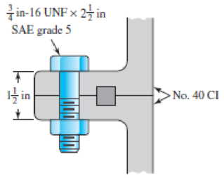
Problem 8–60
(a) Determine the yielding factor of safety.
(b) Determine the overload factor of safety.
(c) Determine the factor of safety based on joint separation.
(d) Determine the fatigue factor of safety using the Goodman criterion.
Expert Solution & Answer
Want to see the full answer?
Check out a sample textbook solution
Students have asked these similar questions
The figure gives the cross-section of a grade 25 cast-iron pressure vessel. A total of N bolts are to be used to resist a separating force of 150 kN.
(a) Determine kb, km, and C.
(b) Find the number of bolts required for a load factor of 2 where the bolts may be reused when the joint is taken apart.
(c) With the number of bolts obtained in part (b), determine the realized load factor for overload, the yielding factor of safety, and the load factor for joint separation.
Use (SI) units as it applies
Figure 8-19 is a cross-section of ASTM A36. A total of N bolts are to be used to resist a separating force of 7258.97N is one bolt.
A) Determine kb,km, and C
B) Determine the realized load factor for overload, the yielding factor of safety, and the load factor of joint separation.
A 0.5-in.-diameter steel [E= 30,000 ksi] bolt (1) is placed in a copper tube (2). The copper [E= 16,000 ksi] tube has an outside diameter of 1.00 in., a wall thickness of 0.125 in., and a length of L= 8.0 in. Rigid washers, each with a thickness of t= 0.125 in., cap the ends of the copper tube. The bolt has 20 threads per inch. This means that each time the nut is turned one complete revolution, the nut advances 0.05 in. (i.e., 1/20 in.). The nut is hand-tightened on the bolt until the bolt, nut, washers, and tube are just snug, meaning that all slack has been removed from the assembly but no stress has yet been induced. What stresses are produced in the bolt and in the tube if the nut is tightened an additional quarter turn past the snug-tight condition?
Chapter 8 Solutions
SHIGLEY'S MECH.ENGIN....(LOOSE)>CUSTOM<
Ch. 8 - A power screw is 25 mm in diameter and has a...Ch. 8 - Using the information in the footnote of Table...Ch. 8 - Show that for zero collar friction the efficiency...Ch. 8 - A single-threaded power screw is 25 mm in diameter...Ch. 8 - The machine shown in the figure can be used for a...Ch. 8 - The press shown for Prob. 8-5 has a rated load of...Ch. 8 - For the screw clamp shown, a force is applied at...Ch. 8 - The C clamp shown in the figure for Prob. 8-7 uses...Ch. 8 - Find the power required to drive a 1.5-in power...Ch. 8 - A single square-thread power screw has an input...
Ch. 8 - Prob. 11PCh. 8 - An M14 2 hex-head bolt with a nut is used to...Ch. 8 - Prob. 13PCh. 8 - A 2-in steel plate and a 1-in cast-iron plate are...Ch. 8 - Repeat Prob. 8-14 with the addition of one 12 N...Ch. 8 - A 2-in steel plate and a 1-in cast-iron plate are...Ch. 8 - Two identical aluminum plates are each 2 in thick,...Ch. 8 - Prob. 18PCh. 8 - A 30-mm thick AISI 1020 steel plate is sandwiched...Ch. 8 - Prob. 20PCh. 8 - Prob. 21PCh. 8 - Prob. 22PCh. 8 - A 2-in steel plate and a 1-in cast-iron plate are...Ch. 8 - An aluminum bracket with a 12-in thick flange is...Ch. 8 - An M14 2 hex-head bolt with a nut is used to...Ch. 8 - A 34 in-16 UNF series SAE grade 5 bolt has a 34-in...Ch. 8 - From your experience with Prob. 8-26, generalize...Ch. 8 - Prob. 28PCh. 8 - Prob. 29PCh. 8 - Prob. 30PCh. 8 - For a bolted assembly with eight bolts, the...Ch. 8 - Prob. 32PCh. 8 - 8-33 to 8-36 The figure illustrates the...Ch. 8 - 8-33 to 8-36 The figure illustrates the...Ch. 8 - 8-33 to 8-36 The figure illustrates the...Ch. 8 - 8-33 to 8-36 The figure illustrates the...Ch. 8 - Prob. 37PCh. 8 - Prob. 38PCh. 8 - 837 to 840 Repeat the requirements for the problem...Ch. 8 - Prob. 40PCh. 8 - 841 to 844 For the pressure vessel defined in the...Ch. 8 - Prob. 42PCh. 8 - Prob. 43PCh. 8 - Prob. 44PCh. 8 - Bolts distributed about a bolt circle are often...Ch. 8 - The figure shows a cast-iron bearing block that is...Ch. 8 - Prob. 47PCh. 8 - Prob. 48PCh. 8 - Prob. 49PCh. 8 - Prob. 50PCh. 8 - 851 to 854 For the pressure cylinder defined in...Ch. 8 - Prob. 52PCh. 8 - 851 to 854 For the pressure cylinder defined in...Ch. 8 - 851 to 854 For the pressure cylinder defined in...Ch. 8 - 855 to 858 For the pressure cylinder defined in...Ch. 8 - 855 to 858 For the pressure cylinder defined in...Ch. 8 - 855 to 858 For the pressure cylinder defined in...Ch. 8 - For the pressure cylinder defined in the problem...Ch. 8 - A 1-in-diameter hot-rolled AISI 1144 steel rod is...Ch. 8 - The section of the sealed joint shown in the...Ch. 8 - Prob. 61PCh. 8 - Prob. 62PCh. 8 - Prob. 63PCh. 8 - Prob. 64PCh. 8 - Using the Goodman fatigue criterion, repeat Prob....Ch. 8 - The figure shows a bolted lap joint that uses SAE...Ch. 8 - Prob. 67PCh. 8 - A bolted lap joint using ISO class 5.8 bolts and...Ch. 8 - Prob. 69PCh. 8 - The figure shows a connection that employs three...Ch. 8 - A beam is made up by bolting together two cold...Ch. 8 - Prob. 72PCh. 8 - Prob. 73PCh. 8 - Prob. 74PCh. 8 - A vertical channel 152 76 (see Table A7) has a...Ch. 8 - The cantilever bracket is bolted to a column with...Ch. 8 - Prob. 77PCh. 8 - The figure shows a welded fitting which has been...Ch. 8 - Prob. 79PCh. 8 - Prob. 80PCh. 8 - Prob. 81P
Knowledge Booster


Learn more about
Need a deep-dive on the concept behind this application? Look no further. Learn more about this topic, mechanical-engineering and related others by exploring similar questions and additional content below.Similar questions
- A right angled bell crank lever is to be designed to raise a load of 5 kN at the short arm end. The lengths of short and long arms are 100 and 450 mm respectively. The lever and the pins are made of steel 30C8 (S = 400 N/mm2). And the factor of safety is 5.the permissible bearing pressure on the pin is 10 N/mm². The lever has a rectangular cross section and the ratio of width to thickness is 3:1. The length to diameter ratio of the fulcrum pin is 1.25:1. Calculate (i) The diameter and length of the fulcrum pin (ii) The dimensions of the cross section.arrow_forwardThe layout of transmission shaft carrying two pulleys B and C and supported on bearings A and D is shown in Figure below. Power is supplied to the shaft by means of a vertical belt on pulley B, that is then transmitted to pulley C carrying a horizontal belt. The maximum tension in belt on pulley B is 2.5 kN. The angle of wrap for both the pulleys is 180o and the coefficient of friction 0.24. The shaft is made of plain carbon steel 30C8 (Syt=400 N/mm2) and the factor of safety is 3. Determine the shaft diameter on strength basis.arrow_forward3. Design a compression coupling for a shaft to transmit 1300 N-m. The allowable shear stress for the shaft and key is 40 MPa and the number of bolts connecting the two halves are 4. The permissible tensile stress for the bolts material is 70 MPa. The coefficient of friction between the muff and the shaft surface may be taken as 0.3.arrow_forward
- A rectangular plate of width b-40 mm and thickness s 20 mm has a hole with a diameter d=8 mm in the center. As shown in the figure, the plate is statically loaded to F = 15,000 N. What would be the smallest S safety factor that will occur? Select a suitable steel from Table A-3.2-4 as the material of the plate.arrow_forward7. Design a muff coupling for joining shafts transmitting 8 kW at 400 rpm. The shaft and the key are made of steel with 45 MPa and 80 MPa allowable stresses in shear and crushing, respectively. The material of the sleeve is CI, with allowable shear stress 10 MPa. Service factor KS =1.2.arrow_forwardThe rotating shaft running at n = 900 rpm, shown in the figure below, is machined from AISI 1045 CD steel. It is subjected to a force of F = 10.1 kN. The shaft is experiencing an operating temperature of 35 oC. With the specified loading and for the reliability of 99.9 %, Determine the minimum factor of safety for fatigue based on infinite life*. Determine the maximum safe load (Fmax) that can be applied for a factor of safety of 1.5 and a design life of 5x10⁵ cycles, all other input values remaining the same. Determine the factor of safety against yielding.arrow_forward
- A rigid coupling with 30 inches of bolt circle diameter transmits a torque of 18,000 lb-in. The coupling material has a yield strength of 90,000 psi. The coupling is fastened by six bolts. Assume design factor of N=3 Calculate the diameter of each bolt.arrow_forwardA semi-elliptic spring used for automobile suspension, consists of two extra full-length leaves and eight graduated-length leaves, including the master leaf. The centre-to centre distance between the two eyes is 1 m. The leaves are made of steel 55Si2Mo90 (Syt = 1500 N/mm2and E = 207000 N/mm2) and the factor of safety is 2. The maximum spring load is 30 kN. The leaves are pre- stressed so as to equalize stresses in all leaves under maximum load. Determine the dimensions of the cross-section of the leaves and the deflection at the end of the spring.arrow_forwardProblem 3. A solid round bar is to be assembled into a collar by press fitting. The inside radius of the collar is R = 50 mm and the outside radius is o = 4C mm. Find the maximum allowable radial interference 3 if the assembly is to have a safety factor of 2 against yielding. Both parts are made of carbon steel having E 200 GPa and Sy = 300MPa Solve using the DET. ↑ Oarrow_forward
- A 2.5 cm x 7.5 cm steel beam with a length of 61 cm is subjected to a reversed load of 17.8 kN at midpoint. If yield stress and endurance stress are 410 MPa and 155 MPa respectively, what should be the minimum factor of safety? A helical spring has a free length of 203 mm, outside diameter of 115 mm and a wire diameter of 13 mm. It consist of 9.5 coils squared and grounded at the ends. If it is compressed to its solid length, what is the stress in the spring? Let G = 80 GPa.arrow_forwardDesign a cast iron type flange coupling to transmit 15 kW at 900 rpm from an electric motor to a compressor. Take shear stress for shaft, bolt and key material as 40 MPa.arrow_forwardA rotating shaft of 25-mm diameter is simply supported by bearing reaction forces R1 and R2. The shaft is loaded with a transverse load of 13 kN as shown in the figure. The shaft is made from AISI 1045 hot-rolled steel. The surface has been machined. Determine a) The minimum static factor of safety based on yielding b) the endurance limit adjusted as necessary with Marin factors c) the minimum fatigue factor of safety based on achieving infinite life d) if the fatigue factor of safety is less than 1, then estimate the life of the part in number of rotationsarrow_forward
arrow_back_ios
SEE MORE QUESTIONS
arrow_forward_ios
Recommended textbooks for you
 Mechanics of Materials (MindTap Course List)Mechanical EngineeringISBN:9781337093347Author:Barry J. Goodno, James M. GerePublisher:Cengage Learning
Mechanics of Materials (MindTap Course List)
Mechanical Engineering
ISBN:9781337093347
Author:Barry J. Goodno, James M. Gere
Publisher:Cengage Learning
Mechanical SPRING DESIGN Strategy and Restrictions in Under 15 Minutes!; Author: Less Boring Lectures;https://www.youtube.com/watch?v=dsWQrzfQt3s;License: Standard Youtube License