
Concept explainers
Videos
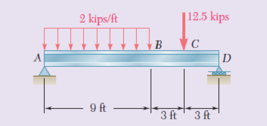
(a) Knowing that σall = 24 ksi and σall = 14.5 ksi, select the most economical wide-flange shape that should be used to support the loading shown. (b) Determine the values to be expected for τm, τm, and the principal stress σmax at the junction of a flange and the web of the selected beam.
Fig. P8.65
(a)
Select the most economical wide flange shape section.
Answer to Problem 65RP
The most economical wide flange shape section is
Explanation of Solution
Given information:
The allowable bending stress
The shear stress
Calculation:
Sketch the free body diagram of beam as shown in figure 1.
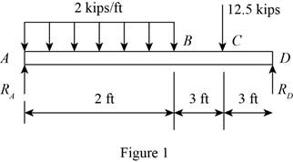
Here,
Calculate the reaction for the given structure:
Taking moment about D,
Summation of vertical force zero.
Calculate the shear force diagram as follows:
Shear force at A is
Shear force at B,
Shear force at C,
Shear force at D,
Maximum shear force occurs at the point where
Consider a section
Calculate the bending moment as follows:
Bending moment at point A,
Bending moment at point B,
Bending moment at point C,
Bending moment at point D,
Sketch the shear force and bending moment diagram as shown in Figure 2.
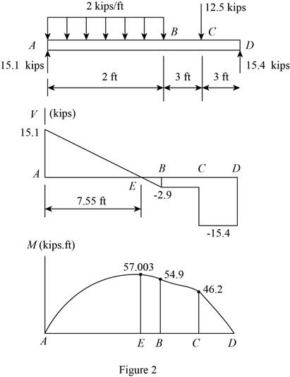
Refer to Figure 2.
The maximum bending moment is
Find the value of
Here,
Substitute
Write the section properties shape as shown in Table 2.
| Shape | |
| 38.4 | |
| 29.0 | |
| 33.4 | |
| 32.4 | |
| 31.2 |
Select the section
The most economical wide flange shape section is
Write the section properties wide flange section as shown in Table 3.
| Shape | W14x22 |
| Area, A | |
| Depth, d | |
| Web thickness, | 0.230 in. |
| Width | 5.000 in. |
| Thickness | 0.335 in. |
Find the area of web
Here, d is the depth of the section and
Substitute
(b)
The value to be expected for
Answer to Problem 65RP
The normal stress
The shear stress
The maximum principal stress is
Explanation of Solution
Calculation:
Point E:
Find the normal stress at point E using the relation:
Here,
Substitute
Thus, the normal stress
Find the value of C using the relation:
Here, d is the depth of section.
Substitute
Find the value of
Here,
Substitute
Find the normal stress
Here,
Substitute
Find the shear stress
The point E is located at top. Since Q is zero.
Thus, the shear stress at point
Point C:
Find the normal stress at point E using the relation:
Here,
Substitute
Find the shear stress point C using the relation:
Here, V is shear force and
Substitute
Thus, the shear stress
Find the
Substitute
Find the R using the relation:
Here,
Substitute
Find the maximum principal stress using the relation:
Substitute
Compare the results,
Select the maximum value of stress for Point B is controls.
Thus, the maximum principal stress is
Want to see more full solutions like this?
Chapter 8 Solutions
Mechanics of Materials, 7th Edition


- A cast-iron tube is used to support a compressive load. Knowing that E5 10 3 106 psi and that the maximum allowable change in length is 0.025%, determine (a) the maximum normal stress in the tube, (b) the minimum wall thickness for a load of 1600 lb if the outside diameter of the tube is 2.0 in.arrow_forwardThe driveshaft of an automobile is being designed to transmit 238 hp at 3790 rpm. Determine the minimum diameter d required for a solid steel shaft if the allowable shear stress in the shaft is not to exceed 5700 psi.arrow_forwardKnowing that a 0.02-in. gap exists when the temperature is 75°F, determine (a) the temperature at which the normal stress in the alumi-num bar will be equal to –11 ksi, (b) the corresponding exact length of the aluminum bar.arrow_forward
- Knowing that connecting rod BD has a uniform cross section of area equal to 800 mm², determine the magnitude of the load P so that the normal stress in rod BD is 50 MPa.arrow_forwardTwo forces P can be applied separately or at the same time to a plate that is welded to a solid circular bar of radius r. Determine the largest compressive stress in the circular bar (a) when both forces are applied, (b) when only one of the forces is applied.arrow_forwardIn the steel structure shown, a 6-mm-diameter pin is used at C and10-mm-diameter pins are used at B and D. The ultimate shearing stress is 150 MPa at all connections, and the ultimate normal stress is 400 MPa in link BD. Knowing that a factor of safety of 3.0 is desired,determine the largest load P that can be applied at A. Note that link BD is not reinforced around the pin holes.arrow_forward
- In the steel structure shown, a 6-mm-diameter pin is used at C and 12-mm-diameter pins are used at B and D. The ultimate shearing stress is 150 MPa at all connections, and the ultimate normal stress is 350 MPa in link BD. Knowing that a factor of safety of 3.0 is desired, determine the largest load P that can be applied at A. Note that link BD is not reinforced around the pin holes. The largest load P that can be applied at A is kN.arrow_forwardA standard-weight steel pipe of 12-in. nominal diameter carries water under a pressure of 400 psi. (a) Knowing that the outside diameter is 12.75 in. and the wall thickness is 0.375 in., determine the maximum tensile stress in the pipe. (b) Solve part a, assuming that an extra-strong pipe is used, of 12.75-in. outside diameter and 0.5-in. wall thickness.arrow_forwardTwo links BF are made of steel with a 450-MPa ultimate normal stress and has a 6x12–mm uniform rectangular cross section. Links BF are connected to members ABD and CDEF by 8-mm diameter pins; ABD and CDEF are connected together by a 10-mm diameter pin; CDEF is connected to the support by a 10-mm diameter pin; all of the pins are made of steel with a 170 MPa ultimate shearing stress. Knowing that a factor of safety of 3 is desired, determine the largest load P that may be appliedarrow_forward
- Determine the largest axial load P that can be safely supported by a flat steel bar consisting of two portions, both 10 mm thick and, respectively, 40 and 60 mm wide, connected by fillets of radius r=8 mm. Assume an allowable normal stress of 165 MPa.arrow_forwardSolve Prob A rod consisting of two cylindrical portions AB and BC is restrained at both ends. Portion AB is made of steel (Es5 29 3 106 psi, αs5 6.5 3 10–6/°F) and portion BC is made of aluminum (Ea5 10.4 3 106psi, αa5 13.3 3 10–6/°F). Knowing that the rod is initially unstressed, determine (a) the normal stresses induced in portions AB and BC by a temperature rise of 70°F, (b) the corresponding deflection of point B assuming that portion AB of the composite rod is made of aluminum and portion BC is made of steel.arrow_forwardKnowing that the average normal stress in member CE of the Pratt bridge truss shown must not exceed 21 ksi for the given loading,determine the cross-sectional area of that member that will yield the most economical and safe design. Assume that both ends of the member will be adequately reinforcedarrow_forward
 Elements Of ElectromagneticsMechanical EngineeringISBN:9780190698614Author:Sadiku, Matthew N. O.Publisher:Oxford University Press
 Mechanics of Materials (10th Edition)Mechanical EngineeringISBN:9780134319650Author:Russell C. HibbelerPublisher:PEARSON
 Thermodynamics: An Engineering ApproachMechanical EngineeringISBN:9781259822674Author:Yunus A. Cengel Dr., Michael A. BolesPublisher:McGraw-Hill Education
 Control Systems EngineeringMechanical EngineeringISBN:9781118170519Author:Norman S. NisePublisher:WILEY
 Mechanics of Materials (MindTap Course List)Mechanical EngineeringISBN:9781337093347Author:Barry J. Goodno, James M. GerePublisher:Cengage Learning
 Engineering Mechanics: StaticsMechanical EngineeringISBN:9781118807330Author:James L. Meriam, L. G. Kraige, J. N. BoltonPublisher:WILEY