
Theory and Design for Mechanical Measurements
6th Edition
ISBN: 9781118881279
Author: Richard S. Figliola, Donald E. Beasley
Publisher: WILEY
expand_more
expand_more
format_list_bulleted
Videos
Textbook Question
Chapter 8, Problem 8.14P
The thermocouple circuit in Figure 8.45 represents a J-type thermocouple with the reference junction having 72=0 °C. The output voltage is 13.777 mV. What is the temperature of the measuring junction, T\1
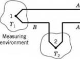

Figure 8.45 Thermocouple circuit for Problems 8.14 through 8.16; (1) measuring junction; (2) reference junction.
Expert Solution & Answer
Want to see the full answer?
Check out a sample textbook solution
Students have asked these similar questions
. thermodynamics-
A platinum resistance thermometer has a resistance of 5 ohm at 0°C and 2.5 ohm at 100°C Calculate the temperature when the resistance indicated is 10 ohm.
A chromel-constantan type thermocouple has a cold junction (or cold terminal) at the temperature of 20ºC. The tables provide the following values for this thermocouple: 0°C for e.m.f = 0.000 mV; 20ºC for e.m.f = 1192 mV and 200ºC for e.m.f = 13419 mV. To determine:(a) The Seebeck coefficient (or proportionality constant) of this thermocouple.
(b) The electrical voltage at the thermocouple terminals when the hot junction (or terminal hot) is at a temperature of 200ºC.
A thermocouple with test junction at t°C on gas thermometer scale and Reference junction at ice point gives the e.m.f. as e = 0.20 t – 5 × 10^–4t^2 mV. The millivoltmeter is calibrated at ice and steam points. What will be the reading on this Thermometer where the gas thermometer reads 70°C ?
Chapter 8 Solutions
Theory and Design for Mechanical Measurements
Ch. 8 - Prob. 8.1PCh. 8 - Fixed temperature points in the International...Ch. 8 - Answers to the following questions may be found in...Ch. 8 - Calculate the resistance of a platinum wire that...Ch. 8 - Plot the resistance of a platinum wire that is 5 m...Ch. 8 - An RTD forms one arm of a Wheatstone bridge, as...Ch. 8 - An RTD forms one arm (/?4) of a Wheatstone bridge,...Ch. 8 - Research and describe current state-of-the-art...Ch. 8 - Prob. 8.9PCh. 8 - 8.10 Estimate the required level of uncertainty in...
Ch. 8 - 8.11 A thermistor is placed in a 100 °C...Ch. 8 - Prob. 8.12PCh. 8 - Prob. 8.13PCh. 8 - The thermocouple circuit in Figure 8.45 represents...Ch. 8 - The thermocouple circuit in Figure 8.45 represents...Ch. 8 - The thermocouple circuit in Figure 8.45 is...Ch. 8 - 8.17 a. The thermocouple shown in Figure 8.46a...Ch. 8 - Prob. 8.18PCh. 8 - Prob. 8.19PCh. 8 - A temperature measurement requires an uncertainty...Ch. 8 - A temperature difference of 3.0 °C is measured...Ch. 8 - Complete the following table for a J-type...Ch. 8 - Complete the following table for a T-type...Ch. 8 - Prob. 8.24PCh. 8 - 8.25 You are employed as a heating, ventilating,...Ch. 8 - A J-type thermocouple for use at temperatures...Ch. 8 - A J-type thermocouple is calibrated against an RTD...Ch. 8 - A beaded thermocouple is placed in a duct in a...Ch. 8 - Consider a welded thermocouple bead that...Ch. 8 - Prob. 8.30PCh. 8 - Prob. 8.31PCh. 8 - Consider the typical construction of a sheathed...Ch. 8 - An iron-constantan thermocouple is placed in a...Ch. 8 - Figure 8.48 Schematic diagram for Problems 8.33,...Ch. 8 - Figure 8.48 Schematic diagram for Problems 8.33,...Ch. 8 - 8.36 In Example 8.5, an uncertainty value for Rf...Ch. 8 - The thermocouple circuit shown in Figure 8.49...Ch. 8 - Prob. 8.38PCh. 8 - 8.39 A thin-film heat flux sensor employs a K-type...Ch. 8 - A thin-film heat flux sensor has a sensitivity uV...Ch. 8 - 8.41 A T-type thermopile is used to measure...Ch. 8 - 8.42 A T-type thermocouple referenced to 0 °C is...Ch. 8 - A T-type thermocouple referenced to 0 °C develops...Ch. 8 - 8.44 A temperature measurement system consists of...
Knowledge Booster


Learn more about
Need a deep-dive on the concept behind this application? Look no further. Learn more about this topic, mechanical-engineering and related others by exploring similar questions and additional content below.Similar questions
- Use appropriate diagram and sketches. When the cold junction of a thermocouple thermometer is at 0° C and the hot junction at 100°C the millivoltmeter shows a deflection of 4.2 mV towards the left. The cold junction is now put in an unknown temperature while maintaining the hot junction at 100°C. The millivoltmeter now shows a deflection of 5.2 mV towards the right. Calculate the unknown temperaturearrow_forwardA thermocouple has an output emf as shown in the following table when its hot (measuring) junction is at the temperatures shown. Determine the sensitivity of measurement for the thermocouple in mv/"C. Temperature (C) 3.5 13 4 12 Voltage imv) Sensitivity, Sarrow_forwardPROBLEM 4: (See example 8.6) A J-type thermocouple is used to measure an unknown temperature. The reference junction, T2, is at 71 F. The voltmeter reads 18.743 mV. What is the T1 junction temperature?arrow_forward
- (Q4) A thermopile 18 constructed with Iron-constantan materials. Four junctions are maintained at 300°C and for junctions are maintained at 40°C. The output of the thermopile is connected to a potentiometer. What voltage will be indicated if both terminals of the potentiometer are at the same temperature? What is the temperature indicated in this case?arrow_forwardA type K , chromel-alumel, thermocouple has a hot-junction temperature of 237 oC and a cold junction temperature of 28 oC. What is the output voltage (mv) if the thermocouple has no cold junction voltage compensation? A. 8.504 B. 10.748 C. 9.626 D. 10.552 E. 9.712arrow_forwardThe following resistance of a platinum resistance thermometer were measured at a range of temperature. Determine the measurement sensitivity of the instrument in milli Ohms/ oC. Resistance (mῼ) Tempreture (oC) 210k 110 217k 89 221k 68 228k 47arrow_forward
- A load cell is calibrated in an environment at a temperature of 21°C and has the following deflcction/load characteristic: Load (kg) 0 50 100 150 200 Deflection (mm) 0.0 1.0 2.0 3.0 4.0 When used in an environment at 35°C, its characteristic changes to the following: Load (kg) 0 50 100 150 200 Deflection (mm) 0.2 1.3 2.4 3.5 4.6 Determine the sensitivity at 21°C and 35°C. Calculate the total zero drift and sensitivity drift at 35°C. Hence determine the zero drift and sensitivity drift coefficients (in units of pm/°C and (pm per kg)/(°C)).arrow_forwardTwo large containers A and B of the same size are filled with different fluids. The fluids in containers A and B are maintained at 0° C and 100° C, respectively. A small metal bar, whose initial temperature is 100° C, is lowered into container A. After 1 minute the temperature of the bar is 90° C. After 2 minutes (since being lowered into container A) the bar is removed and instantly transferred into the other container. After 1 minute in container B the temperature of the bar rises 10°. How long, measured from the start of the entire process, will it take the bar to reach 99.5° C? (Round your answer to two decimal places. Assume the final temperature being asked for is reached while the bar is container B.)arrow_forwardIn the measurement with the thermoeleman circuit, whose voltage-temperature relation is linear and the calibration coefficient is 0.05 mV/ºC, it was understood that the temperature of the reference end is higher than 0ºC after the measurement point temperature is calculated as 80ºC. To resolve this error, this time the measuring tip was immersed in the water-ice mixture and a deviation of 0.15 mV was observed at the millivolt meter. How many ° C is the first value measured as 80 ° C? a. 76.25 b. 77.50 c. 78.00 d. 75.00 e. 77.00arrow_forward
- Explain the significance of the following information given in the specification of the followingtransducer,Thermocouple Sensitivity: nickel chromium/nickel aluminum thermocouple: 0.039 mV/ºC when thecold junction is at 0 ºC.arrow_forwardThe transducer specified in Table 1.1 is chosen to measurea nominal pressure of 500 cm H2O. The ambient temperature is expected to vary between 18 ∘C and 25 ∘C duringtests. Estimate the possible range (magnitude) of each listedelemental error affecting the measured pressure. How do I calculate the sensitivity error? The solution that was given: Sensitivity error(eK) = (±0.0025)(500 cm H2O)= ± 0.75 cm H2O = ± 0.00375 V My Question is, how do you obtain 0.75 since 0.0025 x 500 gives 1.25! please help. thanksarrow_forwardKindly provide a detailed solution of the problem. The thermometer reading 700F is placed in an oven preheated to a constanttemperature. After 1⁄2 minute, the thermometer reads 1100 F and it reads 1450F after 1minute. What is the temperature in the oven?arrow_forward
arrow_back_ios
SEE MORE QUESTIONS
arrow_forward_ios
Recommended textbooks for you
 Principles of Heat Transfer (Activate Learning wi...Mechanical EngineeringISBN:9781305387102Author:Kreith, Frank; Manglik, Raj M.Publisher:Cengage Learning
Principles of Heat Transfer (Activate Learning wi...
Mechanical Engineering
ISBN:9781305387102
Author:Kreith, Frank; Manglik, Raj M.
Publisher:Cengage Learning
Heat Transfer – Conduction, Convection and Radiation; Author: NG Science;https://www.youtube.com/watch?v=Me60Ti0E_rY;License: Standard youtube license