
Theory and Design for Mechanical Measurements
6th Edition
ISBN: 9781118881279
Author: Richard S. Figliola, Donald E. Beasley
Publisher: WILEY
expand_more
expand_more
format_list_bulleted
Videos
Textbook Question
Chapter 8, Problem 8.34P
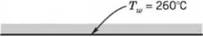
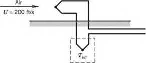

Figure 8.48 Schematic diagram for Problems 8.33, 34, and 35.
8.34 An iron-constantan thermocouple is placed in a moving air stream in a duct, as shown in Figure 8.48. The air flows at 70 m/s. The emissivity of the thermocouple is 0.5 and the recovery factor is 0.6. The wall temperature, Twis 300 °C. The thermocouple reference junction is maintained at 100 °C. The emf output from the thermocouple is 16 mV.
- Determine the thermocouple junction temperature.
- By considering recovery and radiation errors, estimate the possible value for total error in the indicated temperature. Discuss whether this estimate of the measurement error is conservative and why, or why not. The heat-transfer coefficient may be taken as 100 W/m2K.
Expert Solution & Answer
Want to see the full answer?
Check out a sample textbook solution
Students have asked these similar questions
A vertical-tube two-pass heater is used for heating gas oil. Saturated steam at 100 lbf/in^2 gauge is used as a heating medium. The tubes are 1 in. OD by BWG 16 and are made of mild steel. The oil enters at 60°F and leaves at 150°F. The viscosity-temperature relation is exponential. The viscosity at 60°F is 5.0 cP and at 150°F is 1.8 cP. The oil is 37° API (specific gravity 0.840) at 60°F. The flow of oil is 150 bbl/h (1 bbl = 42 gal). Assume the steam condenses in film condensation. The thermal conductivity of the oil is 0.078 Btu/ft-h-°F, and the specific heat is 0.480 Btu/1b-°F. The velocity of the oil in the tubes should be approximately 4 ft/s. Calculate the length of tubes needed for this heater.
The figure 1 above presents a crudely simplified centralised water heating system. The system comprises of two heating lines, the first line having one radiatorand the second has four radiators in series.The pressure after the pump (point (1)) is 2 bar, and the flow velocity is 1.2 m/s. For simplicity we can assume the water to be in constant temperature of 60◦C. Loss coefficients and pressure losses are listed in Table 1, and pipe lengths and diameters are given in Table 2.For the system balancing, the target is to divide the mass flow so, so that 20% of the mass flow goes to the first line (i.e. through radiator R1.1) and 80% of the flow goes to the second line (R2.1 - R2.4):(a) How large pressure loss is needed in the control valve CV1 to get the desired flow rates in the two lines? (b) How large is then the minor loss coefficient of the said valve, KCV1? (c) How much is the pressure, in bar, at the end of the line at section 4?
Catalogue data of a water-cooled condenser of a manufacturer gives the following details:
Condensing temperature 48.9°C
Water inlet temperature 37.8°C
Water flow rate 20.694 kg/s
Capacity 145 tons
Estimate the capacity of this condenser with the same water flow rate but with an inlet temperature of 30°C and a condensation temperature of 42°C. The evaporation temperature may be assumed to be constant at 2.2°C.
Chapter 8 Solutions
Theory and Design for Mechanical Measurements
Ch. 8 - Prob. 8.1PCh. 8 - Fixed temperature points in the International...Ch. 8 - Answers to the following questions may be found in...Ch. 8 - Calculate the resistance of a platinum wire that...Ch. 8 - Plot the resistance of a platinum wire that is 5 m...Ch. 8 - An RTD forms one arm of a Wheatstone bridge, as...Ch. 8 - An RTD forms one arm (/?4) of a Wheatstone bridge,...Ch. 8 - Research and describe current state-of-the-art...Ch. 8 - Prob. 8.9PCh. 8 - 8.10 Estimate the required level of uncertainty in...
Ch. 8 - 8.11 A thermistor is placed in a 100 °C...Ch. 8 - Prob. 8.12PCh. 8 - Prob. 8.13PCh. 8 - The thermocouple circuit in Figure 8.45 represents...Ch. 8 - The thermocouple circuit in Figure 8.45 represents...Ch. 8 - The thermocouple circuit in Figure 8.45 is...Ch. 8 - 8.17 a. The thermocouple shown in Figure 8.46a...Ch. 8 - Prob. 8.18PCh. 8 - Prob. 8.19PCh. 8 - A temperature measurement requires an uncertainty...Ch. 8 - A temperature difference of 3.0 °C is measured...Ch. 8 - Complete the following table for a J-type...Ch. 8 - Complete the following table for a T-type...Ch. 8 - Prob. 8.24PCh. 8 - 8.25 You are employed as a heating, ventilating,...Ch. 8 - A J-type thermocouple for use at temperatures...Ch. 8 - A J-type thermocouple is calibrated against an RTD...Ch. 8 - A beaded thermocouple is placed in a duct in a...Ch. 8 - Consider a welded thermocouple bead that...Ch. 8 - Prob. 8.30PCh. 8 - Prob. 8.31PCh. 8 - Consider the typical construction of a sheathed...Ch. 8 - An iron-constantan thermocouple is placed in a...Ch. 8 - Figure 8.48 Schematic diagram for Problems 8.33,...Ch. 8 - Figure 8.48 Schematic diagram for Problems 8.33,...Ch. 8 - 8.36 In Example 8.5, an uncertainty value for Rf...Ch. 8 - The thermocouple circuit shown in Figure 8.49...Ch. 8 - Prob. 8.38PCh. 8 - 8.39 A thin-film heat flux sensor employs a K-type...Ch. 8 - A thin-film heat flux sensor has a sensitivity uV...Ch. 8 - 8.41 A T-type thermopile is used to measure...Ch. 8 - 8.42 A T-type thermocouple referenced to 0 °C is...Ch. 8 - A T-type thermocouple referenced to 0 °C develops...Ch. 8 - 8.44 A temperature measurement system consists of...
Knowledge Booster


Learn more about
Need a deep-dive on the concept behind this application? Look no further. Learn more about this topic, mechanical-engineering and related others by exploring similar questions and additional content below.Similar questions
- In an absorption refrigerator, the energy driving the process is sllPplied not as work, but as heat from a gas flame. (Such refrigerators commonly use propane as fuel, and are used in locations where electricity is unavailable. *) Let us define the following symbols, all taken to be positive by definition: Qf = heat input from flame Qe = heat extracted from inside refrigerator Qr = waste heat expelled to room Tf = temperature of flame Te temperature inside refrigerator Tr = room temperature Explain why the "coefficient of performance" (COP) for an absorption refrigerator should be defined as Qc/Qf.arrow_forwardA condenser of a steam power plant indicates a vacuum of 65 cm of Hg when barometer reads 75 cm Hg. The condensing steam has a temperature of 45 o C and a dryness fraction 0.9. Calculate: (i) the amount of air to be handled by the pump per min. if the rate of steam condensation is 2000 kg/hr. (ii) vacuum efficiency of the condenser.arrow_forwardThe large insulated flash chamber of a vacuum refrigeration plant is kept at low temperatureby a steam jet which pumps vapor to a condenser . The condensate pump removes thecondensate formed and an air ejector discharges air from the condenser to an air vent .Warm water returns enters the flash chamber at 13 deg C ; chilled water leaves the flashchamber at 4 deg C . The vapor leaving the flash chamber has a dryness factor of 97% andthe condenser inside temperature is 32 deg C . For 100 tons of refrigeration , determine thequantity in cubic meter per minute of chilled water at 4 deg C that the system can provide .A) 0.45 B) 0.56 C) 9.33 D) 0.75arrow_forward
- A steam line carries 200t/h of steam at 40bar connected to a control volume of a spray type desuperheater which is supplied with another line of water at 50 C. Calculate the amount of water that must be sprayed per second to maintain steam at 400 C (at outlet line) when the boiler load causes the first line of steam to leave at 450 C.arrow_forwardDescribe the mechanism of heat loss in the following scenarios. A computer chip on a motherboard is cooled continuously using a small fan to maintain a constant temperature Heat transfer from an uninsulated heat exchanger to the surrounding work environment Heat transfer inside a pepsi can placed in a refrigerator Heat transfer from a moving car to the driverarrow_forwardPROBLEM 4: (See example 8.6) A J-type thermocouple is used to measure an unknown temperature. The reference junction, T2, is at 71 F. The voltmeter reads 18.743 mV. What is the T1 junction temperature?arrow_forward
- Project 4: Pipe lagging is an insulation fitted around pipes to maintain energy loss at minimum and prevent any freezing or bursting. Your part in the HTU thermodynamics and heat transfer lab is to conduct an experiment to explore the heat losses that would occur in both lagged and unlagged hot water pipe. The required tools and main apparatus are shown in Figure.4 and general schematic is shown in Fugure.5. Figure.1, shows the pump for providing running the cycle, thermocouple for measuring the temperature and the pipe coil. Your lab instructor asked you to perform the following tasks: • Fit the lagging around the pipe • Connect the pump to inlet of coil • Measure the hot water terampere at the inlet (make sure the temperature reaches its steady state before measuring it) • Operate the cycle by turn on the pump • Measure the cold water terampere at the outlet in steady state. • Repeat the previous step with unlagged pipe • Search for an appropriate video where a test to measure the…arrow_forwardA liquid-to-gas counterflow heat exchanger is used to cool gas from 32°C to 18°C. Assuming that the liquid enters at 7°C and leaves at 15°C, calculate the log mean temperature difference in °C. Draw and label the temperature-flow diagram. Round off your answer to three (3) decimal places.arrow_forward(a) Compare flat plate, parabolic collectors to be used for a solar thermal plant with respect to (i) temperature, (ii) concentration ratio, (iii) suitability, and (iv) absorber type. (b) A tidal power plant of single basin type, has a basin area of 25 x 10 to power 6 m2. The tide has a range of 10m. The turbine however, stops operating when the head on it falls below 2 m. Calculate the energy generated in one filling process, in KWh if the turbine generator efficiency is 75%. (Density of sea water = 1025 kg/m2)arrow_forward
- In an absorption refrigerator, the energy driving the process is sllPplied not as work, but as heat from a gas flame. (Such refrigerators commonly use propane as fuel, and are used in locations where electricity is unavailable. *) Let us define the following symbols, all taken to be positive by definition: Qf = heat input from flame Qe = heat extracted from inside refrigerator Qr = waste heat expelled to room Tf = temperature of flame Te temperature inside refrigerator Tr = room temperature Use the second law of thermodynamics to derive an upper limit on the COP, in terms of the temperatures Tf, Te, and Tr alone.arrow_forwardThe Lithium Bromide water absorption cycle shown in the figure operates at the following temperatures: Generator, 5°C; Condenser, 35°C; Evaporators, 5°C; and Absorber, 30°C. The flow rate of solution delivered by the pump is 0.4 kg/sec. Determine the following: What is the amount of heat, in kilowatts, rejected at the absorber? a. 71.8 b. 287.4 c. 205.3 d. 146.4 e. 104.5 What is the Absorber System Coefficient of Performance, in percentile? a. 146.4 b. 71.8 c. 205.3 d. 104.5 e. 287.4 What is the mass flow rate, in kg/sec, of the fluid at line 5? a. 0.129 b. 0.252 c. 0.180 d. 0.353 e. 0.092arrow_forwardA chromel-constantan type thermocouple has a cold junction (or cold terminal) at the temperature of 20ºC. The tables provide the following values for this thermocouple: 0°C for e.m.f = 0.000 mV; 20ºC for e.m.f = 1192 mV and 200ºC for e.m.f = 13419 mV. To determine:(a) The Seebeck coefficient (or proportionality constant) of this thermocouple. (b) The electrical voltage at the thermocouple terminals when the hot junction (or terminal hot) is at a temperature of 200ºC.arrow_forward
arrow_back_ios
SEE MORE QUESTIONS
arrow_forward_ios
Recommended textbooks for you
 Principles of Heat Transfer (Activate Learning wi...Mechanical EngineeringISBN:9781305387102Author:Kreith, Frank; Manglik, Raj M.Publisher:Cengage Learning
 Refrigeration and Air Conditioning Technology (Mi...Mechanical EngineeringISBN:9781305578296Author:John Tomczyk, Eugene Silberstein, Bill Whitman, Bill JohnsonPublisher:Cengage Learning
Principles of Heat Transfer (Activate Learning wi...
Mechanical Engineering
ISBN:9781305387102
Author:Kreith, Frank; Manglik, Raj M.
Publisher:Cengage Learning
Refrigeration and Air Conditioning Technology (Mi...
Mechanical Engineering
ISBN:9781305578296
Author:John Tomczyk, Eugene Silberstein, Bill Whitman, Bill Johnson
Publisher:Cengage Learning
The Refrigeration Cycle Explained - The Four Major Components; Author: HVAC Know It All;https://www.youtube.com/watch?v=zfciSvOZDUY;License: Standard YouTube License, CC-BY