
Concept explainers
Videos
A cylindrical tank with hemispherical heads is constructed of steel sections that are welded circumferentially (see figure). The tank diameter is 1.25 m, the wall thickness is 22 mm, and the internal pressure is 1750 kPa,
(a) Determine the maximum tensile stress
(b) Determine the maximum tensile stress
(c) Determine the tensile stress <7W acting perpendicular to the welded joints,
(d) Determine the maximum shear stress rtiin the heads of the tank.
(e) Determine the maximum shear stress tcin the cylindrical part of the tank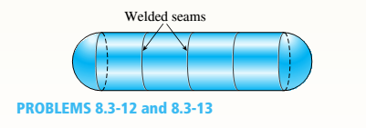

Trending nowThis is a popular solution!

Chapter 8 Solutions
Bundle: Mechanics Of Materials, Loose-leaf Version, 9th + Mindtap Engineering, 1 Term (6 Months) Printed Access Card


- A hemispherical window (or viewport) in a decompression chamber (see figure) is subjected to an internal air pressure of 85 psi. The window is attached to the wall of the chamber by 14 bolts. (a) Find the tensile force Fin each bolt and the tensile stress (T in the viewport if the radius of the hemisphere is 14 in. and its thickness is 1.25 in. (b) If the yield stress for each of the 14 bolts is 50 ksi and the factor of safety is 3.0, Find the required bolt diameter. (c) If the stress in the viewport is limited to 500 psi, find the required radius of the hemisphere.arrow_forward: A cylindrical tank with diameter d = 18 in, is subjected to internal gas pressure p = 450 psi. The tank is constructed of steel sections that arc welded circum fereiitially (sec figure). The heads of the tank are hemispherical. The allowable tensile and shear stresses are 8200 psi and 3000 psi, respectively. Also, the allowable tensile stress perpendicular to a weld is 6250 psi. Determine the minimum required thickness /minof (a) the cylindrical part of the tank and (b) the hemispherical heads.arrow_forward: A hollow, pressurized sphere having a radius r = 4.8 in, and wall thickness t = 0.4 in. is lowered into a lake (see figure). The compressed air in the tank is at a pressure of 24 psi (gage pressure when the tank: is out of the water). At what depth D0will the wall of the tank be subjected to a compressive stress of 90 psi?arrow_forward
- The hollow drill pipe for an oil well (sec figure) is 6,2 in. in outer diameter and 0.75 in. in thickness. Just above the bit, the compressive force in the pipe (due to the weight of the pipe) is 62 kips and the torque (due to drilling) is 185 kip-in. Determine the maximum tensile, compressive, and shear stresses in the drill pipe.arrow_forwardA hollow, circular, cast-iron pipe (Ec =12,000 ksi) supports a brass rod (Ec= 14,000 ksi} and weight W — 2 kips, as shown. The outside diameter of the pipe is dc= 6 in. (a) If the allowable compressive stress in the pipe is S00O psi and the allowable shortening of the pipe is 0.02 in., what is the minimum required wall thickness trmm? (Include the weights of the rod and steel cap in your calculations.) (b) What is the elongation of the brass rod Srdue to both load Wand its own weight? (c) What is the minimum required clearance h?arrow_forwardA spherical tank of diameter 48 in. and wall thickness 1.75 in. contains compressed air at a pressure of 2200 psi. The tank is constructed of two hemispheres joined by a welded seam (see figure). (a) What is the tensile load/ (lb per in. of length of weld) carried by the weld? (b) What is the maximum shear stress rm2Xin the wall of the tank? (c) What is the maximum normal strain e in the wall? (For steel, assume E = 30 X 10 psi and v = 0.29.)arrow_forward
- A sign is supported by a pipe (see figure) having an outer diameter 110 mm and inner diameter 90 mm. The dimensions of the sign are 2.0 m X 1.0 m, and its lower edge is 3.0 m above the base. Note that the center of gravity of the sign is 1.05 m from the axis of the pipe. The wind pressure against the sign is 1.5 kPa. Determine the maximum in-plane shear stresses due to the wind pressure on the sign at points /I, B, and C, located on the outer surface at the base of the pipe.arrow_forwardA pressurized circular cylinder has a sealed cover plate fastened with steel bolts (see figure). The pressure P of the gas in the cylinder is290psi, the inside diameter D of the cylinder is 10.0 in., and the diameter dBof the bolts is 0.50 in. I f the allowable tensile stress in the bolts is 10,000 psi, find the number n of bolts needed to fasten the cover.arrow_forwardProblem 2: (M2) Design engineers in many situations must justify their selection of material. Your role in a mechanical design company that manufactures steel pipes is to confirm the maximum stresses imposed by a 250 psi oil pressure on the pipe wall, which acts as a pressurized cylinder once the gate valve is closed. If the pipe diameter is 1 foot and its wall is 0.25 inches thick. Evaluate the longitudinal and hoop stresses at point A. Valve A oil in Figure.3: Steel oil pipearrow_forward
- A wood-stave pipe is bound by steel rods which take the untire bursting stress. Find the proper spacing for 8-mm diameter steel rod for a 1.80-m diameter wood stave pipe if the working stress is 60 mpa for a head of water of 20m.arrow_forward(b) Determine the thickness of a plain cylinder head for 0.3m cylinder. The maximum gas pressure is approximately 3.2N/mm. Design the studs also for the cylinder cover. Assume the allowable hoop stress =42 N/mm' for cast iron; the allowable tensile stress for material of studs =63 N/mm?arrow_forwardThe tank shown in the figure shown is fabricated from a steel plate. a. Determine the maximum longitudinal stress caused by an internal pressure of 1.2MPA if the steel plate has a thickness of 10mm. b. Determine the maximum circumferential stress caused by an internal pressure of 1.2MPA, if the stress plate has a thickness of 10mm. c. Determine the minimum thickness plate which maybe used if the stress is limited to 40MPA and the internal pressure is 1.5MPA. 1400 mm 400 mm 600 mmarrow_forward
 Mechanics of Materials (MindTap Course List)Mechanical EngineeringISBN:9781337093347Author:Barry J. Goodno, James M. GerePublisher:Cengage Learning