
Videos
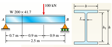
A W 200 x 41.7 wide-flange beam (see Table F-l(b), Appendix F) is simply supported with a span length of 2.5 m (see figure). The beam supports a concentrated load of 100 kN at 0.9 m from support B. At a cross section located 0,7 m from the left-hand support, determine the principal stresses tr, and
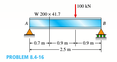
(a).
To find: Values of maximum stress and principal shear stress at top of beam.
Answer to Problem 8.4.16P
Values of principal stress :
Maximum shear stress
Explanation of Solution
Given Information:
Beam length
Point load
Dimensions of beam,
Concept Used:
Bending stress
Shear stress
Values of principal normal stress :
Maximum shear stress:
From equilibrium:
So, bending moment at point
Shear force at point
Moment of inertia:
First, moment of area at the top of beam shall be zero,
So, bending stress at top:
And shear stress at that point:
For this situation no stress in
Values of Principal and normal stress are given by following equation:
Maximum shear stress:
Conclusion:
Hence, we get:
Values of principal stress :
Maximum shear stress
(b).
To find: The values of principal stress and principal stress at top of web.
Answer to Problem 8.4.16P
Values of principal stress:
Maximum shear stress:
Explanation of Solution
Given Information:
Beam length
Point load
Dimensions of beam,
Concept Used:
Bending stress
Shear stress
Values of principal normal stress:
Maximum shear stress

From equilibrium:
So, bending moment at point
Shear force at point
Moment of inertia:
First, moment of area of flange:
So, bending stress at top of web:
And shear stress at that point ::
For this situation no stress in
Values of principal normal stress are given by following equation:
Maximum shear stress,
Conclusion:
Hence, we get:
Values of principal stress :
Maximum shear stress
(c).
To find: Values of principal stress and maximum stress at neutral axis.
Answer to Problem 8.4.16P
Values of principal stress:
Maximum shear stress
Explanation of Solution
Given Information:
Beam length
Point load
Dimensions of beam:
Concept Used:
Bending stress
Shear stress
Principal normal stresses
Maximum shear stress

From equilibrium:
So, bending moment at point
Shear force at point
Moment of inertia,
First moment of area for the section above the neutral axis:
So, bending stress at neutral axis:
And shear stress at that point:
For this situation no stress in
Values of principal stress are given by following equation:
Maximum shear stress:
Conclusion:
Hence, we get:
Values of principal stress:
Maximum shear stress
Want to see more full solutions like this?
Chapter 8 Solutions
Bundle: Mechanics Of Materials, Loose-leaf Version, 9th + Mindtap Engineering, 1 Term (6 Months) Printed Access Card


- A beam with a wide-flange cross section (see figure) has the following dimensions: h = 120 mm, r = 10 mm, h = 300 mm, and /ij = 260 mm. The beam is simply supported with span length L = 3,0 im A concentrated load P = 120 kN acts at the midpoint of the span. At across section located 1.0 m from the left-hand support, determine the principal stresses tr, and tr2and the maximum shear stress Tmax at each of the following locations: (a) the top of the beam, (b) the top of the web, and (c) the neutral axisarrow_forwardA W 12 X 14 wide-flange beam (see Table F-l(a), Appendix F) is simply supported with a span length of 120 in. (see figure). The beam supports two anti-symmetrically placed concentrated loads of 7,5 kips each. At a cross section located 20 in. from the right-hand support, determine the principal stresses (7]and (7\ and the maximum shear stress Tmaw at each of the following locations: (a) the top of the beam, (b) the top of the web, and (c) the neutral axis,arrow_forwardA beam with a wide-flange cross section (see figure) has the following dimensions: b = 5 in., t = 0.5 in,, ft = 12 in., and /?, = 10.5 in. The beam is simply supported with span length L = 10 ft and supports a uniform load q = 6 kips/fL Calculate the principal stresses *rl and and the maximum shear stress t__ at a cross section located [|] JA 3 ft from the left-hand support at each of the following locations: (a) the bottom of the beam, (b) the bottom of the web, and (c) the neutral axisarrow_forward
- The composite beam shown in the figure is simply supported and carries a total uniform load of 40 kN/m on a span length of 4.0 m. The beam is built of a southern pine wood member having cross-sectional dimensions of 150 mm × 250 mm and two brass plates of cross-sectional dimensions 30 mm × 150 mm. Determine the maximum stresses (7b and ctwin the brass and wood, respectively, if the moduli of elasticity are EB= % GPa and Ew= 14 GPa. (Disregard the weight of the beam.) Find the required thickness of the brass plates so that the plate and wood reach their allowable stress values of Eb= 70 MPa and t Ew= 8.5 MPa simultaneously under the maximum moment. What is the maximum moment?arrow_forwardA bimetallic beam used in a temperature-control switch consists of strips of aluminum and copper bonded together as shown in the figure, which is a cross-sectional view. The width of the beam is LO in,, and each strip has a thickness of 1/16 in. Under the action of a bending moment M = 12 lb-in, acting about the z axis, what are the maximum stresses aaand ecin the aluminum and copper, respectively? (Assume fA, = 10,5 x l0 psi and ecu= 16,8 × 10⁶ psi,)arrow_forwardA wood beam with a rectangular cross section (see figure) is simply supported on a span of length L. The longitudinal axis of the beam is horizontal, and the cross section is tilted at an angle a. The load on the beam is a vertical uniform load of intensity q acting through the centroid C. Determine the orientation of the neutral axis and calculate the maximum tensile stress bmaxif PROBLEMS 6.4-2 and 6.4-3 b = 80 mm, b = 140 mm, L = 1,75 m, a — 22.5°, and q = 7.5 kN/m.arrow_forward
- A simply supported wide-flange beam of span length L carries a vertical concentrated load P acting through the centroid Cat the midpoint of the span (see figure). The beam is attached to supports inclined at an angle « to the horizontal. Determine the orientation of the neutral axis and calculate the maximum stresses at the outside corners of the cross section (points A, B. ZX and E) due to the load P. Data for the beam are W 250 x 44,8 section, L = 3.5 m, P = 18 kN, and a = 26,57 Note: See Table F-l(b) of Appendix F for the dimensions and properties of the beam.arrow_forwardA cantilever beam(Z, = 6 ft) with a rectangular cross section (/> = 3.5 in., h = 12 in.) supports an upward load P = 35 kips at its free end. (a) Find the state of stress ((7T, o^., and r in ksi) on a plane-stress element at L/2 that is i/ = 8 in. up from the bottom of the beam. Find the principal normal stresses and maximum shear stress. Show these stresses on sketches of properly oriented elements. (b) Repeat part (a) if an axial compressive centroidal load N = 40 kips is added at Barrow_forwardA simple beam of span length 3.2 m carries a uniform load of intensity 48 kN/m, The cross section of the beam is a hollow box with wood flanges and steel side plates, as shown in the figure. The wood flanges are 75 mm x 100 mm in cross section, and the steel plates are 300 mm deep. What is the required thickness t of the steel plates if the allowable stresses are 120 M Pa for the steel and 6,5 M Pa for the wood? (Assume that the moduli of elasticity for the steel and wood are 210 GPa and 10 GPa, respectively, and disregard the weight of the beam.)arrow_forward
- A reinforced concrete slab (see figure) is reinforced with 13-mm bars spaced 160 mm apart at d = 105 mm from the top of the slab. The modulus of elasticity for the concrete is Ec= 25 GPa, while that of the steel is £s = 200 G Pa. Assume that allowable stresses for concrete and steel arecrac = 9.2 MPa and us = 135 MPa. l()5 mm Find the maximum permissible positive bending moment for a l-m wide strip of the slab. What is the required area of steel reinforcement, A^ if a balanced condition must be achieved? What is the allowable positive bending moment? (Recall that in a balanced design, both steel and concrete reach allowable stress values simultaneously under the design moment.)arrow_forwardA W 310 x 52 steel beam is subjected to a point load P = 45 kN and a transverse load V = 20 kN at B. The beam has length L =2m.(a) Calculate the principal normal stresses and the maximum shear stress on element D located on the web right below the top flange and near the fixed support. Neglect the weight of the beam, (b) Repeat Part a atcentroid C (sec figure). See Table F-l(b), Appendix F, for beam propertiesarrow_forwardA canti lever beam A B of a n isosceles t rapezoi-dal cross section has a length L = 0.8 m, dimensions bx= 80 mm and b2= 90 mm, and height h = 110 mm (see figure). The beam is made of brass weighing 85 kN/m3. Determine the maximum tensile stress asand maximum compressive stressarrow_forward
 Mechanics of Materials (MindTap Course List)Mechanical EngineeringISBN:9781337093347Author:Barry J. Goodno, James M. GerePublisher:Cengage Learning