
Concept explainers
Videos
A crank arm consists of a solid segment of length bxand diameter rf, a segment of length bltand a segment of length byas shown in the figure. Two loads P act as shown: one parallel to — vand another parallel to —y. Each load P equals 1.2 kN. The crankshaft dimensions are A] = 75 mm, fr> = 125 mm, and b3= 35 mm. The diameter of the upper shaft isd = 22 mm,
(a) Determine the maximum tensile, compressive, and shear stresses at point A, which is located on the surface of the shaft at the z axis.
(b) Determine the maximum tensile, compressive, and shear stresses at point B, which is located on the surface of the shaft at the y axis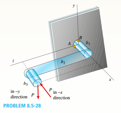

Trending nowThis is a popular solution!

Chapter 8 Solutions
Bundle: Mechanics Of Materials, Loose-leaf Version, 9th + Mindtap Engineering, 1 Term (6 Months) Printed Access Card


- Repeat Problem 6.4-14 but use the configuration of channel shapes and loading shown in the figure. Use P = 250 N.arrow_forwardRepeat Problem 11.2-3 assuming that R= 10 kN · m/rad and L = 2 m.arrow_forwardA crank shaft is operated as shown in the figure. A load F1 = 9.73 N is applied and the operator %3D dz applies a load P to counter. The system is in equilibrium and all of the bearings are perfectly dz aligned such that they do not produce moments on the rotating crank. The geometry is given by, w = 7.31 [m), dl = 9.69 m], d2 = 7.57 m). 6.14 (m), d5 = 3.7 (m), %3D d1 d3 = 9.87 (m), d4 %3D F2 and h1 4.4 (m), find the following: %3D F1 Part 1. Express the reaction forces exerted on the bar by the journal bearing at point B. Use the coordinate system shown in the diagram 10 5% 100% Submit [N] Part 2. Express the reaction forces exerted on the bar by the journal bearing at Point A. Use the coordinate system shown in the diagram. 5% 100% 10 Submit [N]arrow_forward
- In the figure, the machine element located at the C point in the transmission system is radial and axial loads. These loads; Fr: 500 daN, Fa = 250 daN in addition to this .Testing the load of the machine element affects the spindle once again up to 100 daN. Loads in the system A and B are covered by a single row ball bearing. By evaluating what is given; a-) Calculate the forces acting on the bearings and the required shaft diameter. b-) Choose the most optimum bearing so that the life of the A bearing will be at least 4000 hours. For the shaft material in the system; oem = 7 daN/mm2, bearings will operate with 1000 rpm rotation speed. Important Note: Axial Load will be carried by the A-bearing Fa Fr A В 200mm 180mm 220mmarrow_forwardA part of the structure for a facory automation system is a beam that spans 30.0 inches as shown below. Loads that are applied at two points each 8.0inches from a support. The left load F1=1800 lb remains constantly applied while the right load F2=1800 lb is applied and removed frequently as the machine cycles. Find the following: Maximum stress Minimum stress Mean stress Alternating stress Stress ratio Solve the missing parameters in complete solution put necessary diagrams if needed. Thanksarrow_forwardThe figure attached shows a crank loaded by a force F=300 lbf that causes twisting and bending of 3/4 -in-diameter shaft fixed to a support at the origin of reference system. Calculate the following: The internal forces at A, B, and C. Refer to the FBD figure and table provided below. All units shall be in lbf-in for moments and torques, lbf for forces. Determine the maximum normal and shear stress at A. DRAW THE STRESS ELEMENT/S AND SHOW APPROPRIATE FORCES. Units shall be in ksi.arrow_forward
- As seen in the figure, the block on an inclined plane is lifting from 0 0 with two degrees increment in each step. (0, = 0, 0 =2, 02 = 4, ..) Until which degree can we increase the angle without any slipping between the block and the inclined plane? For condition of F > F, the block continues to hang on the inclined plane. Otherwise, it starts to slip. F, = W + sin8(rad), Fy = W+ cosa(rad) F = F, + u, u = 0.50, W = 100 Narrow_forward4- For the shaper mechanism shown in the figure, OA = 50 mm, QB = 350 mm, BC = 170 mm, OQ = 140 mm. Find the displacement slider 6. %3D 120arrow_forward4-67. Figure P4-67 shows a shaft carrying three gears that rotates at 1150 rpm. Gear A delivers 20 kW to a mat- ing gear that drives a mixer. Gear C delivers 12 kW to a different mating gear that drives a circular saw. All power comes into the shaft through gear B. Consider- ing only torsion, compute the shearing stress in each part of the shaft. Consider stress concentrations.arrow_forward
- The machine element located at the C point in the transmission system shown in the figure creates radial and axial loads. These loads; Fr: 500 daN, Fa = 250 daN in addition to thisDue to the weight of the machine element, a further 100 daN load is exerted on the shaft. The loads in the system are met by A and B single row ball radial roller bearings. By evaluating what is given;a-) Calculate the forces acting on the bearings and the required shaft diameter.b-) Choose the most optimum bearing so that the life of the A bearing will be at least 4000 hours. For the shaft material in the system; σsafety=7daN/mm2 bearings will operate at 1000 rpm rotation speed. Important Note: Axial Load will be borne by A bearing.arrow_forwardIn the graph the force versus displacement of a spring is given (the spring is shown in a separate figure--see below). The x-axis range is ±2 cm. The y-axis range is tFs, where Fs = 220 N. How much work does the spring do on the block (the mass "m") when the block moves from x₁ = 7.6 cm to 4.3 cm? W J y F. X -1.5 -0.5 0 10.5 1 1.5 -F How much work does the spring do on the block (the mass "m") when the block moves from x; = 7.6 cm to -7.6 cm? W = Question Help: Read Submit Question marrow_forwardF = F cos # F = F + F F F sin 8. # tan Exampie (1):Find the two components of the force (100 X) if: 0 = 30", 120 270° as shown in figure. F = 100 N F = 100 N 6=30 0 =120° 0 =270 0 = 30 0 =60 F = 100 N lution:arrow_forward
 Mechanics of Materials (MindTap Course List)Mechanical EngineeringISBN:9781337093347Author:Barry J. Goodno, James M. GerePublisher:Cengage Learning