
Concept explainers
Videos
A mountain bike rider going uphill applies a force P = 65 N to each end of the handlebars AB CD, made of aluminum alloy 7075-T6, by pulling on the handlebar extenders (DF on right handlebar segment). Consider the right half of the handlebar assembly only (assume the bars are fixed at the fork at A), Segments AB and CD are prismatic with lengths Lvand L3 and with outer diameters and thicknesses J01, /01 and d03, /03, respectively, as shown. Segment BC of length L2, however, is tapered, and outer diameter and thickness vary linearly between dimensions at B and C Consider shear, torsion, and bending effects only for segment AD; assume DFis rigid.
Find the maximum tensile, compressive, and shear stresses adjacent to support A. Show where each maximum stress value occurs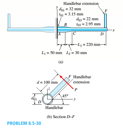

Trending nowThis is a popular solution!

Chapter 8 Solutions
Bundle: Mechanics Of Materials, Loose-leaf Version, 9th + Mindtap Engineering, 1 Term (6 Months) Printed Access Card


- .17 A mountain-bike rider going uphill applies torque T = Fd(F = l5lb, d = 4 in.) to the end of the handlebars ABCD by pulling on the handlebar extenders DE. Consider the right half of the handlebar assembly only (assume the bars are fixed at the fork at A). Segments AB and CD are prismatic with lengths L, = 2 in.andL3 = 8.5 in, and with outer diameters and thicknesses d01 = 1.25 in. 101 = 0.125 in. and d03 = O.87in.,i03 = 0.ll5in, respectively as shown. Segment BC’ of length L, = 1.2 in. however. is tapered, and outer diameter and thickness vary linearly between dimensions at B and C. Consider torsion effects only. Assume G = 4000 ksi is constant. Derive an integral expression for the angle of twist of half of the handlebar tube when it is subjected to torque T = Fd acting at the end. Evaluate ‘b1-, for the given numerical1ues.arrow_forward-7 Repeat Problem 2.3-5, but n include the weight of the bar. See Table I-I in Appendix I for the weight density of steel.arrow_forwardRigid bar ACB is supported by an elastic circular strut DC having an outer diameter of 15 in. and inner diameter of 14.4 in. The strut is made of steel with a modulus elasticity of E = 29,000 ksi. Point load P = 5 kips is applied at B. Calculate the change in length of the circular strut DC. What is the vertical displacement of the rigid bar at point B?arrow_forward
- Compare the angle of twist 1 for a thin-walled circular tube (see figure) calculated from the approximate theory for thin-walled bars with the angle of twist 2 calculated from the exact theory of torsion for circular bars, Express the ratio 12terms of the non-dimensional ratio ß = r/t. Calculate the ratio of angles of twist for ß = 5, 10, and 20. What conclusion about the accuracy of the approximate theory do you draw from these results?arrow_forwardA steel cable with a nominal diameter of 25 mm (see Table 2-1) is used in a construction yard to lift a bridge section weighing 38 kN. as shown in the figure. The cable has an effective modulus of elasticity E = 140 GPa. (a) If the cable is 14 m long, how much will it stretch when the load is picked up? (b) If the cable is rated for a maximum load of 70 kN, that is the factor of safety with respect to failure of the cable?arrow_forwardA copper bar AB with a length 25 in. and diameter 2 in. is placed in position at room temperature with a gap of 0.008 in. between end A and a rigid restraint (see figure). The bar is supported at end B by an elastic spring with a spring constant k= 1.2 × 10⁶ lb/in. (a) Calculate the axial compressive stress crcin the bar if the temperature of the bar only rises 50 F. (For copper, use a = 9.6 × 10⁻⁶/ and E = 16 × 106 psi.) (b) What is the force in the spring? (Neglect gravity effects.) (c) Repeat part (a) if k ? 8.arrow_forward
- A long re Lai nine: wall is braced by wood shores set at an angle of 30° and supported by concrete thrust blocks, as shown in the first part of the figure. The shores are evenly spaced at 3 m apart. For analysis purposes, the wall and shores are idealized as shown in the second part of the figure. Note that the base of the wall and both ends of the shores are assumed to be pinned. The pressure of the soil against the wall is assumed to be triangularly distributed, and the resultant force acting on a 3-meter length of the walls is F = 190 kN. If each shore has a 150 mm X 150 mm square cross section, what is the compressive stressarrow_forwardA hollow circular tube T of a length L = 15 in. is uniformly compressed by a force P acting through a rigid plate (see figure). The outside and inside diameters of the tube are 3.0 and 2.75 in., respectively. A concentric solid circular bar B of 1.5 in. diameter is mounted inside the lube. When no load is present, there is a clearance c = 0.0I0 in. between the bar B and the rigid plate. Both bar and tube are made of steel having an c[autoplastic stress-strain diagram with E = 29 X LO3 ksi and err= 36 ksi. (a) Determine the yield load Pt- and the corresponding shortening 3yof the lube. (b) Determine the plastic load Ppand the corresponding shortening Spof the tube. (c) Construct a load-displacement diagram showing the load Pas ordinate and the shortening 5 of the tube as abscissa. Hint: The load-displacement diagram is not a single straight line in the region 0 ^ P ^ Prarrow_forwardA prismatic bar of length L = 1.8 m and cross-sectional area A = 480 mm" is loaded by forces P{= 30 kN and A = 60 kN (see figure) The bar is constructed of magnesium alloy having a stress-strain curve described by the Ram berg-Osgood equation: 45.000 618 UW id which u has units of mega pascals (MPa). (a) Calculate the displacement 8t- of the end of the bar when the load P:acts alone. (b) Calculate the displacement when the load P, acts alone. (c) Calculate the displacement when both loads act simultaneously.arrow_forward
- Around brass bar of a diameter d1= 20mm has upset ends each with a diameter d2= 26 mm (see figure). The lengths of the segments of the bar are L1= 0.3 m and L2= 0.1 m. Quarter-circular fillets are used at the shoulders of the bar, and the modulus of elasticity of the brass is E = 100 GPa. If the bar lengthens by 0.12 mm under a tensile load P, what is the maximum stress ??maxin the bar?arrow_forwardRepeat Problem 2.4-8, but assume that the bar is made of aluminum alloy and that BC is prismatic. Assume that P = 20 kim. L = 3 ft.t = 314 in., b1 2m.b 2.Sin.andElO.400ksi.arrow_forwardRepeat Problem 11.3-9. Use two C 150 × 12.2 steel shapes and assume that E = 205 GPa and L = 6 m.arrow_forward
 Mechanics of Materials (MindTap Course List)Mechanical EngineeringISBN:9781337093347Author:Barry J. Goodno, James M. GerePublisher:Cengage Learning