
CONTROL SYSTEMS ENGINEERING
7th Edition
ISBN: 9781119185666
Author: NISE
Publisher: WILEY
expand_more
expand_more
format_list_bulleted
Concept explainers
Videos
Textbook Question
Chapter 8, Problem 9P
Figure P8.5 shows open-loop poles and zeros. There are two possibilities for the sketch of the root locus. Sketch each of the two possibilities. Be aware that only one can be the real locus for specific open-loop pole and zero values. [Section: 8.4] 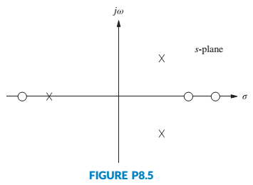
Expert Solution & Answer

Trending nowThis is a popular solution!

Students have asked these similar questions
For the system represented by the following block diagram, Find
a) The Closed-loop Transfer function.
b) Characteristic equation.
c) Type and Order of the system.
c) Time-domain Specifications ( Delay Time, Peak Time, Rise Time, Settling time, and Percentage
overshoot).
R(s)
C(s)
G(s)
H(s)
Where G(s) and H(s) are given as :
324
G(s) =
s(s+6)
H(S) :
1
The open loop transfer function of a humanoid's arm control system is given as:
K
G(s) =
2
s(s + 2s + 2)
(a)
Clearly locate all poles and zeros on a linear graph paper. Provide calculations for
the following: asymptote angles, centroid for asymptotes, and departure angle from
complex pole.
(b)
Plot the complete root locus, with the locus on the real axis is clearly shown. Use
the scale of 4 cm : 1 unit for both axes and choose the longer side of the graph
paper as the real axis.
1. Give an example of open loop and closed loop system (one example each). Also state the input, control system, feedback and output parameter.
Example.
1. Open Loop - Water Heater:
Input - Water Temperature (Cold)
System - Heating Element
Output - Water Temperature (Hot)
2. Closed Loop - Air-conditioning System
Input - Desired Room Temperature
Control - Motor controller/Compressor/ACU
Feedback - Temperature Sensing
Output - Room Temperature
Chapter 8 Solutions
CONTROL SYSTEMS ENGINEERING
Ch. 8 - Prob. 1RQCh. 8 - Prob. 2RQCh. 8 - Prob. 3RQCh. 8 - Prob. 4RQCh. 8 - Prob. 5RQCh. 8 - What are two ways to find where the root locus...Ch. 8 - Prob. 7RQCh. 8 - Prob. 8RQCh. 8 - Prob. 9RQCh. 8 - How would you determine whether or not a root...
Ch. 8 - Prob. 11RQCh. 8 - Prob. 12RQCh. 8 - Prob. 13RQCh. 8 - Prob. 1PCh. 8 - Sketch the general shape of the root locus for...Ch. 8 - Prob. 3PCh. 8 - Let Gs=Ks+23s2s+6 in Figure P8.3. [Section: 8.5]...Ch. 8 - Let Gs=Ks+12s2+2s+2 with K0 in Figure P8.3....Ch. 8 - For the open-loop pole-zero plot shown in Figure...Ch. 8 - Prob. 7PCh. 8 - Prob. 8PCh. 8 - Figure P8.5 shows open-loop poles and zeros. There...Ch. 8 - Prob. 10PCh. 8 - Prob. 11PCh. 8 - Prob. 12PCh. 8 - Prob. 13PCh. 8 - Sketch the root locus and find the range of K for...Ch. 8 - For the unity feedback system of Figure P8.3,...Ch. 8 - Prob. 16PCh. 8 - Prob. 17PCh. 8 - Given the root locus shown in Figure P8.7,...Ch. 8 - Prob. 19PCh. 8 - For the unity feedback system of Figure P8.3,...Ch. 8 - Prob. 21PCh. 8 - Prob. 22PCh. 8 - Prob. 23PCh. 8 - Prob. 24PCh. 8 - Prob. 25PCh. 8 - Prob. 26PCh. 8 - Prob. 28PCh. 8 - Prob. 29PCh. 8 - Prob. 30PCh. 8 - Prob. 31PCh. 8 - For the unity feedback system shown in Figure 8.3,...Ch. 8 - Prob. 34PCh. 8 - Prob. 35PCh. 8 - Prob. 37PCh. 8 - Prob. 38PCh. 8 - Prob. 39PCh. 8 - Prob. 41PCh. 8 - Prob. 42PCh. 8 - Prob. 45PCh. 8 - Repeat Problem 3 but sketch your root loci for...Ch. 8 - Prob. 47PCh. 8 - Prob. 49PCh. 8 - Prob. 50PCh. 8 - Prob. 51PCh. 8 - Prob. 52PCh. 8 - Prob. 53PCh. 8 - Prob. 55PCh. 8 - Prob. 57PCh. 8 - Prob. 58PCh. 8 - Prob. 59PCh. 8 - Wind turbines, such as the one shown in Figure...Ch. 8 - Prob. 62PCh. 8 - Prob. 67PCh. 8 - Prob. 68PCh. 8 - Prob. 70PCh. 8 - Prob. 72P
Knowledge Booster


Learn more about
Need a deep-dive on the concept behind this application? Look no further. Learn more about this topic, mechanical-engineering and related others by exploring similar questions and additional content below.Similar questions
- R(S) K D s+5 Find Open Loop Transfer function XIS s+2 s+3 Y(s)arrow_forward3- Nise (4.4) A unity feedback control system has the following open-loop transfer function: G(s) = 45+¹ Find expressions for 4s+1 45² its time response when is subjected to unit impulse input.arrow_forwardroot locus electrical engineering Don't overthink and reject. Complete the solution as per the given transfer function. No need of quadratic equation just simplify for the exact given transfer function.arrow_forward
- (1) Consider the system represented by the block diagram. The closed loop transfer function T(s)-Y(s)/R(s) is (a) T(s)-50/(s+55 s+50). (b) T(s)=10/(s+50 s+55) (c) T(s)=10/(s+55 s+10). (d) None of the above. R(s)- 10 + s+5 5 Y(s)arrow_forwardFor the system with open loop transfer function given by R(s) K s(s + 1) (s² + 4s +13) where K is the feedback gain. Sketch the root locus a) How many asymptotes are there for this system's root locus? what are asymptote angles? What is the center of asymptotes? C(s) b) Does the root locus cross the imaginary axis? where and what is the value of K at that point? c) Is there any break away, break in points? What is the approximate values of these points?arrow_forwardQUESTION 5 An open-loop transfer function for a root locus is given as: 2K (S + 4) S(S + 2) (S + 8) Use the given transfer function to determine the following: 5.1 The open-loop poles and the zeros G(s)H(s) = Do some of the loci break away? Explain. The centre of asymptotes The asymptotic angles 5.5 The stability of the system 5.2 5.3 5.4arrow_forward
- The Gilles & Retzbach model of a distillation column, the system model includes the dynamics of a boiler, is driven by the inputs of steam flow and the flow rate of the vapour side stream, and the measurements are the temperature changes at two different locations along the column. The state space model is given by: x = 0 00 -30.3 0.00012 -6.02 0 0 0 -3.77 00 0 -2.80 0 0 Is the system?: a. unstable b. C. not unstable x+ 6.15 0 0 0 0 3.04 0 0.052 not asymptotically stable d. asymptotically stable -1 u y = 0 0 0 0 -7.3 0 0 -25.0 Xarrow_forward1) Consider the system below: Vehicle Controller Steering dynamics Desired Actual bearing angle bearing angle 50 1 K s2 + 10s + 50 s(s + 5) Figure 1: Simplified Block Diagram of a Self-Guiding Vehicle's Bearing Angle Control. • Find a K value that the system has minimum rise time and minimum overshoot. Let us call this proportional gain as Kopt Show each step while finding Kopt- Show the necessary graphical solutions. Simulate the system response with 3 different K values. (Kopt and two other K values close to Kopt) Show the system response (actual bearing angle) in a single graph for different K values. • Comment on the results.arrow_forwardFind the equivalent closed loop transfer function for the system R(s) E(s) Y(s) 3 K s+2 10 s+10 (Ctrl)arrow_forward
- Given a state space model [1 1 + 0 u -1 -2 y = [1 1 0] with input u and output y. a). Derive the transfer function representation. b). Derive the differential equations representation. c). Compute the response y(t) with step control input u(t) = 1(t) and zero initial condition. d). and initial condition r(0) = [11 0]". Compute the state response r(t) with control input u(t) = 1(t)arrow_forwardöialg äbäi the open - loop transfer function of the system given as in figure below, what is error steady state * for an input r(t)=1+4t+3t^2 10 (s+1) G(s) s²(5s+6) 3.6 O 5.6 O 7.6 O 10.6 Oarrow_forwardR(S) s+5 Find Closed Loop Transfer function XIS K s+2 s+3 Y(s)arrow_forward
arrow_back_ios
SEE MORE QUESTIONS
arrow_forward_ios
Recommended textbooks for you
 Elements Of ElectromagneticsMechanical EngineeringISBN:9780190698614Author:Sadiku, Matthew N. O.Publisher:Oxford University Press
 Mechanics of Materials (10th Edition)Mechanical EngineeringISBN:9780134319650Author:Russell C. HibbelerPublisher:PEARSON
 Thermodynamics: An Engineering ApproachMechanical EngineeringISBN:9781259822674Author:Yunus A. Cengel Dr., Michael A. BolesPublisher:McGraw-Hill Education
 Control Systems EngineeringMechanical EngineeringISBN:9781118170519Author:Norman S. NisePublisher:WILEY
 Mechanics of Materials (MindTap Course List)Mechanical EngineeringISBN:9781337093347Author:Barry J. Goodno, James M. GerePublisher:Cengage Learning
 Engineering Mechanics: StaticsMechanical EngineeringISBN:9781118807330Author:James L. Meriam, L. G. Kraige, J. N. BoltonPublisher:WILEY
Elements Of Electromagnetics
Mechanical Engineering
ISBN:9780190698614
Author:Sadiku, Matthew N. O.
Publisher:Oxford University Press
Mechanics of Materials (10th Edition)
Mechanical Engineering
ISBN:9780134319650
Author:Russell C. Hibbeler
Publisher:PEARSON
Thermodynamics: An Engineering Approach
Mechanical Engineering
ISBN:9781259822674
Author:Yunus A. Cengel Dr., Michael A. Boles
Publisher:McGraw-Hill Education
Control Systems Engineering
Mechanical Engineering
ISBN:9781118170519
Author:Norman S. Nise
Publisher:WILEY
Mechanics of Materials (MindTap Course List)
Mechanical Engineering
ISBN:9781337093347
Author:Barry J. Goodno, James M. Gere
Publisher:Cengage Learning
Engineering Mechanics: Statics
Mechanical Engineering
ISBN:9781118807330
Author:James L. Meriam, L. G. Kraige, J. N. Bolton
Publisher:WILEY
Introduction to Undamped Free Vibration of SDOF (1/2) - Structural Dynamics; Author: structurefree;https://www.youtube.com/watch?v=BkgzEdDlU78;License: Standard Youtube License