
EBK MECHANICS OF MATERIALS
7th Edition
ISBN: 9780100257061
Author: BEER
Publisher: YUZU
expand_more
expand_more
format_list_bulleted
Concept explainers
Videos
Textbook Question
Chapter 8.2, Problem 18P
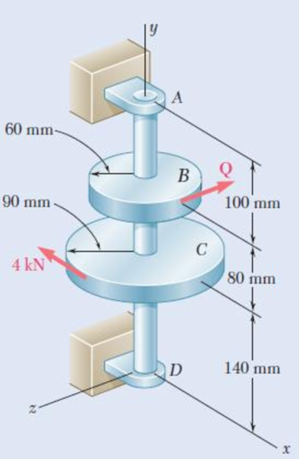
The 4-kN force is parallel to the x axis, and the force Q is parallel to the z axis. The shaft AD is hollow. Knowing that the inner diameter is half the outer diameter and that τall = 60 MPa, determine the smallest permissible outer diameter of the shaft.
Fig. P8.18
Expert Solution & Answer
Want to see the full answer?
Check out a sample textbook solution
Students have asked these similar questions
A
60 mm-
В
90 mm-
100 mm
C
4 kN
80 mm
D
140 mm
An impeller mechanism in a granular material mixing tank is shown. The shaft is hollow with a 2.25" outer
radius. Determine the maximum inner radius allowed (to the nearest ") in order for the angle of rotation of A
with respect to motor C to be 6 degrees maximum and the shear stress to be limited to 10 ksi.
G=11,000 Ks
20 ft
3000 lb-ft
5000 lb-ft
A fabric used in air-inflated structures is subjected to a biaxial loading that results in normal stresses ox = 18 ksi and oz = 24 ksi.Knowing that the properties of the fabric can be approximated as E = 12.6 x 10 psi and v = 0.34, determine the change in length of (a) side AB, (b) side BC, (c) diagonal AC.
Chapter 8 Solutions
EBK MECHANICS OF MATERIALS
Ch. 8.2 - A W10 = 39 rolled-steel beam supports a load P as...Ch. 8.2 - Solve Prob. 8.1, assuming that P = 22.5 kips and a...Ch. 8.2 - An overhanging W920 449 rolled-steel beam...Ch. 8.2 - Solve Prob. 8.3, assuming that P = 850 kN and a =...Ch. 8.2 - 8.5 and 8.6 (a) Knowing that all = 160 MPa and all...Ch. 8.2 - 8.5 and 8.6 (a) Knowing that all = 160 MPa and all...Ch. 8.2 - 8.7 and 8.8 (a) Knowing that all = 24 ksi and all...Ch. 8.2 - 8.7 and 8.8 (a) Knowing that all = 24 ksi and all...Ch. 8.2 - 8.9 through 8.14 Each of the following problems...Ch. 8.2 - 8.9 through 8.14 Each of the following problems...
Ch. 8.2 - 8.9 through 8.14 Each of the following problems...Ch. 8.2 - Prob. 12PCh. 8.2 - 8.9 through 8.14 Each of the following problems...Ch. 8.2 - 8.9 through 8.14 Each of the following problems...Ch. 8.2 - Determine the smallest allowable diameter of the...Ch. 8.2 - Determine the smallest allowable diameter of the...Ch. 8.2 - Using the notation of Sec. 8.2 and neglecting the...Ch. 8.2 - The 4-kN force is parallel to the x axis, and the...Ch. 8.2 - The vertical force P1 and the horizontal force P2...Ch. 8.2 - The two 500-lb forces are vertical and the force P...Ch. 8.2 - Prob. 21PCh. 8.2 - Prob. 22PCh. 8.2 - The solid shaft AB rotates at 600 rpm and...Ch. 8.2 - The solid shaft AB rotates at 600 rpm and...Ch. 8.2 - The solid shafts ABC and DEF and the gears shown...Ch. 8.2 - Prob. 26PCh. 8.2 - Prob. 27PCh. 8.2 - Prob. 28PCh. 8.2 - The solid shaft AE rotates at 600 rpm and...Ch. 8.2 - The solid shaft AE rotates at 600 rpm and...Ch. 8.3 - Two 1.2-kip forces are applied to an L-shaped...Ch. 8.3 - Two 1.2-kip forces are applied to an L-shaped...Ch. 8.3 - The cantilever beam AB has a rectangular cross...Ch. 8.3 - 8.34 through 8.36 Member AB has a uniform...Ch. 8.3 - 8.34 through 8.36 Member AB has a uniform...Ch. 8.3 - 8.34 through 8.36 Member AB has a uniform...Ch. 8.3 - Prob. 37PCh. 8.3 - Two forces are applied to the pipe AB as shown....Ch. 8.3 - Several forces are applied to the pipe assembly...Ch. 8.3 - The steel pile AB has a 100-mm outer diameter and...Ch. 8.3 - Three forces are applied to a 4-in.-diameter plate...Ch. 8.3 - The steel pipe AB has a 72-mm outer diameter and a...Ch. 8.3 - A 13-kN force is applied as shown to the...Ch. 8.3 - A vertical force P of magnitude 60 lb is applied...Ch. 8.3 - Three forces are applied to the bar shown....Ch. 8.3 - Prob. 46PCh. 8.3 - Three forces are applied to the bar shown....Ch. 8.3 - Three forces are applied to the bar shown....Ch. 8.3 - Two forces are applied to the small post BD as...Ch. 8.3 - Two forces are applied to the small post BD as...Ch. 8.3 - Three forces are applied to the machine component...Ch. 8.3 - Prob. 52PCh. 8.3 - Three steel plates, each 13 mm thick, are welded...Ch. 8.3 - Three steel plates, each 13 mm thick, are welded...Ch. 8.3 - Two forces P1 and P2 are applied as shown in...Ch. 8.3 - Two forces P1 and P2 are applied as shown in...Ch. 8.3 - Prob. 57PCh. 8.3 - Four forces are applied to a W8 28 rolled-steel...Ch. 8.3 - A force P is applied to a cantilever beam by means...Ch. 8.3 - Prob. 60PCh. 8.3 - A 5-kN force P is applied to a wire that is...Ch. 8.3 - Knowing that the structural tube shown has a...Ch. 8.3 - The structural tube shown has a uniform wall...Ch. 8.3 - The structural tube shown has a uniform wall...Ch. 8 - (a) Knowing that all = 24 ksi and all = 14.5 ksi,...Ch. 8 - Neglecting the effect of fillets and of stress...Ch. 8 - Knowing that rods BC and CD are of diameter 24 mm...Ch. 8 - The solid shaft AB rotates at 450 rpm and...Ch. 8 - A 6-kip force is applied to the machine element AB...Ch. 8 - A thin strap is wrapped around a solid rod of...Ch. 8 - A close-coiled spring is made of a circular wire...Ch. 8 - Forces are applied at points A and B of the solid...Ch. 8 - Knowing that the bracket AB has a uniform...Ch. 8 - For the post and loading shown, determine the...Ch. 8 - Knowing that the structural tube shown has a...Ch. 8 - The cantilever beam AB will be installed so that...
Knowledge Booster


Learn more about
Need a deep-dive on the concept behind this application? Look no further. Learn more about this topic, mechanical-engineering and related others by exploring similar questions and additional content below.Similar questions
- Knowing that the machine component shown has a trapezoidal cross section with a = 2.5 in. and b = 3.5 in., determine the stress at point A and at point B. Take M = 80 kip·in. The stress at point A is ksi. The stress at point B is ksi.arrow_forwardThe rigid bar ABD is connected to the rod BD which consists of a single bar with a width of 25,0 mm and a thickness of 13 mm. Knowing that each pin has a diameter of 10 mm determine the value of the maximum average normal stress on rod BD considering the angle θ=90°. Calculate the deformation in the BD rod knowing that it is made of steel with an elastic modulus equal to 210GPa. Knowing that pins A, B and D are made of steel with a limit stress of 180Mpa, calculate the smallest allowable diameter so that they support the load applied to them considering an overall safety factor of 2,8.arrow_forwardA steel shaft and an aluminum tube are connected to a fixed support and to a rigid disk as shown in the cross section. Knowing that the initial stresses are zero, determine the maximum torque T0 that can be applied to the disk if the allowable stresses are 120 MPa in the steel shaft and 70 MPa in the aluminum tube. Use G= 77 GPa for steel and G = 27 GPa for aluminum.arrow_forward
- PROBLEM 1 Two forces , each of magnitude P, are applied to the wrench. The diameter of the steel shaft AB is 20 mm. Determine the largest allowable value of P if the shear stress in the shaft is not to exceed 120 MPa and its angle of twist is limited to 7 deg. Use G=80 GPa for steel 300 mm s00 mmarrow_forward5.86 The cast iron inverted T-section supports two concentrated loads of magni- tude P. The working stresses are 48 MPa in tension, 140 MPa in compression, and 30 MPa in shear. (a) Show that the neutral axis of the cross section is located at d = 48.75 mm and that the moment of inertia of the cross-sectional area about this axis is I = 11.918 x 106 mm“. (b) Find the maximum allowable value of P. 1.0 m 1.0 m 15 mm 3 m 150 mm NA- d 15 mm 150 mm FIG. P5.86arrow_forwardThe solid circular drill rod AB is made of a steel that is assumed to be elastoplastic with ry= 22 ksi and G= 11.2 × 10⁶ psi. Knowing that a torque T = 73 kip·in. is applied to the rod and then removed, determine the maximum residual shearing stress in the rod. 35 ft 4 1.2 in. The maximum residual shearing stress in the rod is ksi.arrow_forward
- 2. A steel wire 30 ft long, hanging vertically, supports a load of 500 lbf. Neglecting the weight of the wire, determine the required diameter if the stress is not to exceed 20,000 psi and the total elongation is not to exceed 0. in. Assume E = 29 × 106 psi.arrow_forwardFig. 2 4. A steel shaft of diameter 50 mm and length 1.2 m (E = 210 GPa and v = 0.3) is loaded with multiple force system. At a point in the shaft, the state of stress relative to the x, y, z coordinate system was found to be: [600 0 T = 0 320 MPa -480 (a) Draw a cube element showing the stress components on each coordinate face (Hint: No vector lines for zero stresses; Warning: A stress element without reference axes will receive zero point). (b) From the given stress tensor, determine the values of (i) octahedral normal stress (Goct) and (ii) octahedral shear stress (toct). (c) From your answer in (b), determine (i) dilatational strain energy Udilat '); and (ii) deviatoric strain energy (Udist). (d) Find the total strain energy at the point.arrow_forwardThe rectangular tube shown is extruded from an aluminum alloy for which σY= 40 ksi, σU= 60 ksi, and E= 10.6 * 106 psi. Neglecting the effect of fillets, determine (a) the bending moment M for which the factor of safety will be 3.00 and (b) the corresponding radius of curvature of the tubearrow_forward
- The solid cylinders AB and BC are bonded together at B and are attached to fixed supports at A and C. Knowing that the modulus of rigidity is 3.7×10⁶ psi for aluminum and 5.6x10⁶ psi for brass, determine: 1. The reactions at A and C. 2. The maximum shear in the shaft. 3. The angle of twist in the shaft. Enter your answers in the space provided below is addition to submit your work. Aluminum 12 in. + 1.5 in. B T= 12.5 kip · in. Brass 18 in. - 2.0 in. Edit View Lnsert Format Tools Tahlearrow_forwardDetermine the smallest allowable diameter of the solid shaft ABCD, knowing that τall = 60 MPa and that the radius of disk B is r = 80 mm. Take T = 660 N·m. Determine the smallest allowable diameter of the solid shaft ABCDarrow_forwardThe rigid bar ABC is supported by a pin at A and a steel rod at B. Determine the magnitude of the vertical displacement of point C if the stress in the steel rod is limited to 31.31 ksi, X = 2.55 ft, and Y = 4.75 ft. Neglect the weights of the members. Round off the final answer to four decimal places. ... L = 4 ft A = 0.5 in.2 E = 29 ×106 psi Barrow_forward
arrow_back_ios
SEE MORE QUESTIONS
arrow_forward_ios
Recommended textbooks for you
 Elements Of ElectromagneticsMechanical EngineeringISBN:9780190698614Author:Sadiku, Matthew N. O.Publisher:Oxford University Press
 Mechanics of Materials (10th Edition)Mechanical EngineeringISBN:9780134319650Author:Russell C. HibbelerPublisher:PEARSON
 Thermodynamics: An Engineering ApproachMechanical EngineeringISBN:9781259822674Author:Yunus A. Cengel Dr., Michael A. BolesPublisher:McGraw-Hill Education
 Control Systems EngineeringMechanical EngineeringISBN:9781118170519Author:Norman S. NisePublisher:WILEY
 Mechanics of Materials (MindTap Course List)Mechanical EngineeringISBN:9781337093347Author:Barry J. Goodno, James M. GerePublisher:Cengage Learning
 Engineering Mechanics: StaticsMechanical EngineeringISBN:9781118807330Author:James L. Meriam, L. G. Kraige, J. N. BoltonPublisher:WILEY
Elements Of Electromagnetics
Mechanical Engineering
ISBN:9780190698614
Author:Sadiku, Matthew N. O.
Publisher:Oxford University Press
Mechanics of Materials (10th Edition)
Mechanical Engineering
ISBN:9780134319650
Author:Russell C. Hibbeler
Publisher:PEARSON
Thermodynamics: An Engineering Approach
Mechanical Engineering
ISBN:9781259822674
Author:Yunus A. Cengel Dr., Michael A. Boles
Publisher:McGraw-Hill Education
Control Systems Engineering
Mechanical Engineering
ISBN:9781118170519
Author:Norman S. Nise
Publisher:WILEY
Mechanics of Materials (MindTap Course List)
Mechanical Engineering
ISBN:9781337093347
Author:Barry J. Goodno, James M. Gere
Publisher:Cengage Learning
Engineering Mechanics: Statics
Mechanical Engineering
ISBN:9781118807330
Author:James L. Meriam, L. G. Kraige, J. N. Bolton
Publisher:WILEY
Power Transmission; Author: Terry Brown Mechanical Engineering;https://www.youtube.com/watch?v=YVm4LNVp1vA;License: Standard Youtube License