
EBK MECHANICS OF MATERIALS
7th Edition
ISBN: 9780100257061
Author: BEER
Publisher: YUZU
expand_more
expand_more
format_list_bulleted
Concept explainers
Videos
Textbook Question
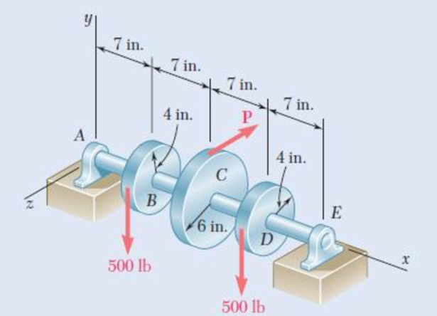
Chapter 8.2, Problem 20P
The two 500-lb forces are vertical and the force P is parallel to the z axis. Knowing that τall = 8 ksi, determine the smallest permissible diameter of the solid shaft AE.
Fig. P8.20
Expert Solution & Answer
Want to see the full answer?
Check out a sample textbook solution
Students have asked these similar questions
7. Knowing that 0=40° and P=9 kN, determine (a) the smallest allowable diameter of the pin at
Bif the average shearing stress in the pin is not exceed 120 MPa, (b) the corresponding average
bearing stress in the member AB at B, (c) the corresponding average bearing stress in each of the
support brackets at B.
P
16 mm
750 mm
750 mm
50 mm-
12 inm
100 mm
75 mm
150 mm
200 mm
100 mm
150 mm
100 mm
CE
PROBLEM 8.29
The solid shaft AE rotates at 600 rpm and
transmits 45 kW from the motor M to machine
tools connected to gears G and H. Knowing that
Tall = 55 MPa and that 30 kW is taken off at gear
G and 15 kW is taken off at gear H, determine the
smallest permissible diameter of shaft AE.
The composite shaft shown is to be twisted by applying a torque T at end A. Knowing that the modulus of rigidity is 77 GPa for the steel and 27 GPa for the aluminum, determine the largest angle through which end A can be rotated if the following allowable stresses are not be exceeded: τsteel= 60 MPa and τaluminum= 45 MPa.
Chapter 8 Solutions
EBK MECHANICS OF MATERIALS
Ch. 8.2 - A W10 = 39 rolled-steel beam supports a load P as...Ch. 8.2 - Solve Prob. 8.1, assuming that P = 22.5 kips and a...Ch. 8.2 - An overhanging W920 449 rolled-steel beam...Ch. 8.2 - Solve Prob. 8.3, assuming that P = 850 kN and a =...Ch. 8.2 - 8.5 and 8.6 (a) Knowing that all = 160 MPa and all...Ch. 8.2 - 8.5 and 8.6 (a) Knowing that all = 160 MPa and all...Ch. 8.2 - 8.7 and 8.8 (a) Knowing that all = 24 ksi and all...Ch. 8.2 - 8.7 and 8.8 (a) Knowing that all = 24 ksi and all...Ch. 8.2 - 8.9 through 8.14 Each of the following problems...Ch. 8.2 - 8.9 through 8.14 Each of the following problems...
Ch. 8.2 - 8.9 through 8.14 Each of the following problems...Ch. 8.2 - Prob. 12PCh. 8.2 - 8.9 through 8.14 Each of the following problems...Ch. 8.2 - 8.9 through 8.14 Each of the following problems...Ch. 8.2 - Determine the smallest allowable diameter of the...Ch. 8.2 - Determine the smallest allowable diameter of the...Ch. 8.2 - Using the notation of Sec. 8.2 and neglecting the...Ch. 8.2 - The 4-kN force is parallel to the x axis, and the...Ch. 8.2 - The vertical force P1 and the horizontal force P2...Ch. 8.2 - The two 500-lb forces are vertical and the force P...Ch. 8.2 - Prob. 21PCh. 8.2 - Prob. 22PCh. 8.2 - The solid shaft AB rotates at 600 rpm and...Ch. 8.2 - The solid shaft AB rotates at 600 rpm and...Ch. 8.2 - The solid shafts ABC and DEF and the gears shown...Ch. 8.2 - Prob. 26PCh. 8.2 - Prob. 27PCh. 8.2 - Prob. 28PCh. 8.2 - The solid shaft AE rotates at 600 rpm and...Ch. 8.2 - The solid shaft AE rotates at 600 rpm and...Ch. 8.3 - Two 1.2-kip forces are applied to an L-shaped...Ch. 8.3 - Two 1.2-kip forces are applied to an L-shaped...Ch. 8.3 - The cantilever beam AB has a rectangular cross...Ch. 8.3 - 8.34 through 8.36 Member AB has a uniform...Ch. 8.3 - 8.34 through 8.36 Member AB has a uniform...Ch. 8.3 - 8.34 through 8.36 Member AB has a uniform...Ch. 8.3 - Prob. 37PCh. 8.3 - Two forces are applied to the pipe AB as shown....Ch. 8.3 - Several forces are applied to the pipe assembly...Ch. 8.3 - The steel pile AB has a 100-mm outer diameter and...Ch. 8.3 - Three forces are applied to a 4-in.-diameter plate...Ch. 8.3 - The steel pipe AB has a 72-mm outer diameter and a...Ch. 8.3 - A 13-kN force is applied as shown to the...Ch. 8.3 - A vertical force P of magnitude 60 lb is applied...Ch. 8.3 - Three forces are applied to the bar shown....Ch. 8.3 - Prob. 46PCh. 8.3 - Three forces are applied to the bar shown....Ch. 8.3 - Three forces are applied to the bar shown....Ch. 8.3 - Two forces are applied to the small post BD as...Ch. 8.3 - Two forces are applied to the small post BD as...Ch. 8.3 - Three forces are applied to the machine component...Ch. 8.3 - Prob. 52PCh. 8.3 - Three steel plates, each 13 mm thick, are welded...Ch. 8.3 - Three steel plates, each 13 mm thick, are welded...Ch. 8.3 - Two forces P1 and P2 are applied as shown in...Ch. 8.3 - Two forces P1 and P2 are applied as shown in...Ch. 8.3 - Prob. 57PCh. 8.3 - Four forces are applied to a W8 28 rolled-steel...Ch. 8.3 - A force P is applied to a cantilever beam by means...Ch. 8.3 - Prob. 60PCh. 8.3 - A 5-kN force P is applied to a wire that is...Ch. 8.3 - Knowing that the structural tube shown has a...Ch. 8.3 - The structural tube shown has a uniform wall...Ch. 8.3 - The structural tube shown has a uniform wall...Ch. 8 - (a) Knowing that all = 24 ksi and all = 14.5 ksi,...Ch. 8 - Neglecting the effect of fillets and of stress...Ch. 8 - Knowing that rods BC and CD are of diameter 24 mm...Ch. 8 - The solid shaft AB rotates at 450 rpm and...Ch. 8 - A 6-kip force is applied to the machine element AB...Ch. 8 - A thin strap is wrapped around a solid rod of...Ch. 8 - A close-coiled spring is made of a circular wire...Ch. 8 - Forces are applied at points A and B of the solid...Ch. 8 - Knowing that the bracket AB has a uniform...Ch. 8 - For the post and loading shown, determine the...Ch. 8 - Knowing that the structural tube shown has a...Ch. 8 - The cantilever beam AB will be installed so that...
Knowledge Booster


Learn more about
Need a deep-dive on the concept behind this application? Look no further. Learn more about this topic, mechanical-engineering and related others by exploring similar questions and additional content below.Similar questions
- A 60 mm- В 90 mm- 100 mm C 4 kN 80 mm D 140 mmarrow_forwardA steel shaft and an aluminum tube are connected to a fixed support and to a rigid disk as shown in the cross section. Knowing that the initial stresses are zero, determine the maximum torque T0 that can be applied to the disk if the allowable stresses are 120 MPa in the steel shaft and 70 MPa in the aluminum tube. Use G= 77 GPa for steel and G = 27 GPa for aluminum.arrow_forwardAn impeller mechanism in a granular material mixing tank is shown. The shaft is hollow with a 2.25" outer radius. Determine the maximum inner radius allowed (to the nearest ") in order for the angle of rotation of A with respect to motor C to be 6 degrees maximum and the shear stress to be limited to 10 ksi. G=11,000 Ks 20 ft 3000 lb-ft 5000 lb-ftarrow_forward
- The ship at A has just started to drill for oil on the ocean floor at a depth of 5000 ft. Knowing that the top of the 8-in.-diameter steel drill pipe (G= 11.2 × 10⁶ psi) rotates through two complete revolu-tions before the drill bit at B starts to operate, determine the maximum shearing stress caused in the pipe by torsionarrow_forwardPROBLEM 1 Two forces , each of magnitude P, are applied to the wrench. The diameter of the steel shaft AB is 20 mm. Determine the largest allowable value of P if the shear stress in the shaft is not to exceed 120 MPa and its angle of twist is limited to 7 deg. Use G=80 GPa for steel 300 mm s00 mmarrow_forwardThe solid circular drill rod AB is made of a steel that is assumed to be elastoplastic with ry= 22 ksi and G= 11.2 × 10⁶ psi. Knowing that a torque T = 73 kip·in. is applied to the rod and then removed, determine the maximum residual shearing stress in the rod. 35 ft 4 1.2 in. The maximum residual shearing stress in the rod is ksi.arrow_forward
- For the steel truss and loading shown, determine the magnitude of the deformation (in inches) of member BE, knowing that the cross-sectional area is 2.42 sq. in, x = 13.9 ft, y = 7.1 ft, P = 27089 lb, and E = 29071219 psi. Round off the final answer to four decimal places.arrow_forwardA milling operation was used to remove a portion of a solid bar of square cross section. Knowing that a= 30 mm, d= 20 mm, and σall= 60 MPa, determine the magnitude P of the largest forces that can be safely applied at the centers of the ends of the bar.arrow_forwardTwo solid steel shafts are connected to fixed supports at A and C and to a disk B. Knowing the modulus of rigidity of the steel is 75 GPa 300 mm and the allowable shear stress is 90 MPa, determine the maximum torque T that can be applied to the disk. 250 mm B 32 mm T. 48 mmarrow_forward
- NEED ANSWER ASAP! For the steel truss and loading shown, determine the magnitude of the deformation (in inches) of member BE, knowing that the cross-sectional area is 2.81 sq. in, x = 13.5 ft, y = 7.8 ft, P = 27565 lb, and E = 29082289 psi.arrow_forwardThe composite shaft shown is to be twisted by applying a torque T at end A. Knowing that the modulus of rigidity is 11.2 x 10⁶ psi for steel and 4 x 10⁶ psi for aluminum, determine the largest angle through which end A may be rotated, if the following allowable stresses are not to be exceeded: steel = 8000 psi and Taluminum = 6700 psi. 2-in. Steel A Aluminum 3 in. 100 in. The largest angle through which end A may be rotated is 0.08arrow_forwardmachine tools connected to gears G and H. Knowing that Tall= 50 Mpa and that 30 kW is taken off at gear G and 15 kW is taken off at gear H, determine the smallest permissible diameter of shaft AE The solid shaft AE rotates at 500 rpm and transmits 45 kW from the motor M to the 100 mm 150 mm 200 mm 150 mm C. 75 mm 100 mm 100 mmarrow_forward
arrow_back_ios
SEE MORE QUESTIONS
arrow_forward_ios
Recommended textbooks for you
 Elements Of ElectromagneticsMechanical EngineeringISBN:9780190698614Author:Sadiku, Matthew N. O.Publisher:Oxford University Press
 Mechanics of Materials (10th Edition)Mechanical EngineeringISBN:9780134319650Author:Russell C. HibbelerPublisher:PEARSON
 Thermodynamics: An Engineering ApproachMechanical EngineeringISBN:9781259822674Author:Yunus A. Cengel Dr., Michael A. BolesPublisher:McGraw-Hill Education
 Control Systems EngineeringMechanical EngineeringISBN:9781118170519Author:Norman S. NisePublisher:WILEY
 Mechanics of Materials (MindTap Course List)Mechanical EngineeringISBN:9781337093347Author:Barry J. Goodno, James M. GerePublisher:Cengage Learning
 Engineering Mechanics: StaticsMechanical EngineeringISBN:9781118807330Author:James L. Meriam, L. G. Kraige, J. N. BoltonPublisher:WILEY
Elements Of Electromagnetics
Mechanical Engineering
ISBN:9780190698614
Author:Sadiku, Matthew N. O.
Publisher:Oxford University Press
Mechanics of Materials (10th Edition)
Mechanical Engineering
ISBN:9780134319650
Author:Russell C. Hibbeler
Publisher:PEARSON
Thermodynamics: An Engineering Approach
Mechanical Engineering
ISBN:9781259822674
Author:Yunus A. Cengel Dr., Michael A. Boles
Publisher:McGraw-Hill Education
Control Systems Engineering
Mechanical Engineering
ISBN:9781118170519
Author:Norman S. Nise
Publisher:WILEY
Mechanics of Materials (MindTap Course List)
Mechanical Engineering
ISBN:9781337093347
Author:Barry J. Goodno, James M. Gere
Publisher:Cengage Learning
Engineering Mechanics: Statics
Mechanical Engineering
ISBN:9781118807330
Author:James L. Meriam, L. G. Kraige, J. N. Bolton
Publisher:WILEY
Power Transmission; Author: Terry Brown Mechanical Engineering;https://www.youtube.com/watch?v=YVm4LNVp1vA;License: Standard Youtube License