
Videos
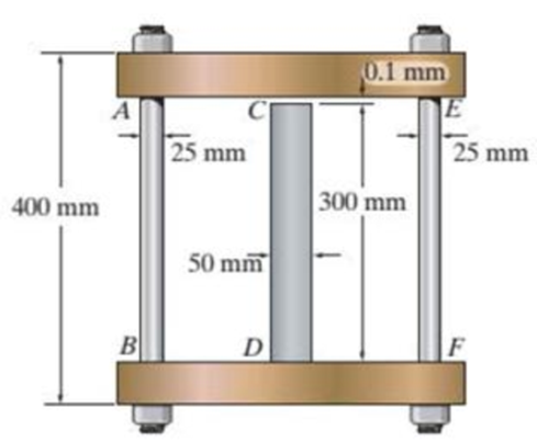
The assembly consists of two A992 steel bolts AB and EF and an 6061-T6 aluminum rod CD. When the temperature is at 30°C, the gap between the rod and rigid member AE is 0.1 mm. Determine the normal stress developed in the bolts and the rod if the temperature rises to 130°C. Assume BF is also rigid.
Prob. R9-1
Find the normal stress developed in the bolts and rod.
Answer to Problem 1RP
The normal stress developed in the bolts and rod are
Explanation of Solution
Given information:
The two bolts AB and EF are made of A992 steel.
The rod CD is made of 6061-T6 aluminum.
The Young’s modulus of the steel is
The Young’s modulus of the aluminum
The coefficient of thermal expansion of the steel
The coefficient of thermal expansion of the aluminum
The initial temperature
The finial temperature
The gap between the rod and rigid member AE is 0.1 mm.
The diameter of the bolts AB and EF
The diameter of the rod CD
The length of the bolts AB and EF
The length of the rod CD
Calculation:
Calculate the area of the bolts AB and EF
Substitute 25 mm for
Calculate the area of the rod CD
Substitute 50 mm for
Calculate the difference of temperature
Substitute
Show the free body diagram of the rigid cap as in Figure 1.
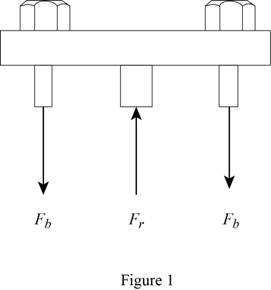
Calculate the vertical forces by applying the equation of equilibrium:
Sum of vertical forces is equal to 0.
Here,
Show the initial and final position of the assembly as in Figure 2.
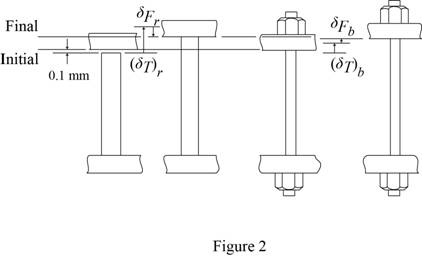
Here
The deformation is as follows:
Substitute
Calculate the force at the bolts AB and EF
Substitute
Calculate the force at the rod CD
Substitute 16,452 N for
Calculate the normal stress developed in the bolts AB and EF
Substitute 16,452 N for
Calculate the normal stress developed in the rod CD
Substitute 32,904 N for
Hence, the normal stress developed in the bolts and rod are
Want to see more full solutions like this?
Chapter 9 Solutions
Statics and Mechanics of Materials - Modified Access


- The 10-mm-diameter steel bolt is surrounded by a bronze sleeve. The outer diameter of this sleeve is 20 mm, and its inner diameter is 10 mm. If the bolt is subjected to a compressive force of P = 20 kN, determine the average normal stress in the steel and the bronze. Est = 200 GPa, Ebr = 100 GPa.arrow_forwardThe cylindrical pressure vessel has an inner radius of 1.25 m and a wall thickness of 15 mm. It is made from steel plates that are welded along the 45° seam. Determine the normal and shear stress components along this seam if the vessel is subjected to an internal pressure of 8 MPa.arrow_forwardThe 50-mm-diameter cylinder is made from Am 1004-T61 magnesium and is placed in the clamp when the temperature is T1 = 20° C. If the 304-stainless-steel carriage bolts of the clamp each have a diameter of 10 mm, and they hold the cylinder snug with negligible force against the rigid jaws, determine the force in the cylinder when the temperature rises to T2 = 130°C.arrow_forward
- The steel pipe is filled with concrete and subjected to a compressive force of 80 kN. Determine the average normal stress in the concrete and the steel due to this loading. The pipe has an outer diameter of 80 mm and an inner diameter of 70 mm. E 200 GPa, Ec= 24 GPa.arrow_forwardAn A-36-steel hoop has an inner diameter of 23.99 in., a thickness of 0.25 in., and a width of 1 in. If it and the 24-in.-diameter A rigid cylinder has a temperature of 65° F, determine the temperature to which the hoop should be heated in order for it to just slip over the cylinder. What is the pressure the hoop exerts on the cylinder, and the tensile stress in the ring when it cools back down to 65° F?arrow_forwardThe cylinder CD of the assembly is heated from T1 = 30°C to T2 = 180°C using electrical resistance. Also, the two end rods AB and EF are heated from T1 = 30°C to T2 = 50°C. At the lower temperature T1 the gap between C and the rigid bar is 0.7 mm. Determine the force in rods AB and EF caused by the increase in temperature. Rods AB and EF are made of steel, and each has a cross-sectional area of 125 mm2. CD is made of aluminum and has a cross-sectional area of 375 mm2. Est = 200 GPa, Eal = 70 GPa, ast = 12(10-6)>°C, and aal = 23(10-6)>°C.arrow_forward
- The two cylindrical rod segments are fixed to the rigid walls such that there is a gap of 0.01 in. between them when T1 = 60°F. Each rod has a diameter of 1.25 in. Determine the average normal stress in each rod if T2 = 400 F, and also calculate the new length of the aluminum segment. Take aal = 13(10-6)>°F, Eal = 10(103) ksi, (sY)al = 40 ksi, acu = 9.4(10-6)>°F, (sY)cu = 50 ksi, and Ecu = 15(103) ksiarrow_forwardThe vertical steel rod has a constant diameter of 32 mm and a length of 400 mm. is hanged from a rigid fixing. A mass is gently placed onto a collar which is attached to the lower end of the rod. The strain energy stored in the steel is 0.400 x 10-³. If Esteet = 209 GPa, 1.1 Determine the gradually applied load and magnitude of the mass. 1.2 Calculate the maximum stress in the rod when gradually applied. 1.3 Determine the magnitude of the mass when the mass is suddenly applied. 1.4 Calculate the extension of the rod when suddenly applied.arrow_forwardThe A-36 steel column, having a cross-sectional area of 10500 mm2, is encased in high-strength concrete as shown. If an axial force of 300kN is applied to the column, determine the compressive stress in the concrete and in the steel. Es = 210GPA and Econc = 29 GPA.arrow_forward
- The bolt has a diameter of 20 (mm) and passes through a tube that has an inner diameter of 50 (mm) and an outer diameter of 60 (mm). If the bolt and tube are made of A-36 steel, determine the normal stress in the tube and bolt when a force of 40 (kN) is applied to the bolt. Assume the end caps are rigid.arrow_forwardThe cylindrical tank with a spherical end cap has an outer radius of 2 m and a wall thickness of 50 mm. If the tank is pressurized to 3.5 MPa, determine the longitudinal and circumferential stresses in the cylinder, and the stress in the end cap. (Show free body diagram and complete solution)arrow_forwardThe spherical pressure vessel has an inner diameter of 2 m and a thickness of 10 mm. A strain gage having a length of 20 mm is attached to it, and it is observed to increase in length by 0.012 mm when the vessel is pressurized. Determine the pressure causing this deformation, and find the maximum in-plane shear stress, and the absolute maximum shear stress at a point on theouter surface of the vessel. The material is steel, for which Est = 200 GPa and nst = 0.3.arrow_forward
 Elements Of ElectromagneticsMechanical EngineeringISBN:9780190698614Author:Sadiku, Matthew N. O.Publisher:Oxford University Press
 Mechanics of Materials (10th Edition)Mechanical EngineeringISBN:9780134319650Author:Russell C. HibbelerPublisher:PEARSON
 Thermodynamics: An Engineering ApproachMechanical EngineeringISBN:9781259822674Author:Yunus A. Cengel Dr., Michael A. BolesPublisher:McGraw-Hill Education
 Control Systems EngineeringMechanical EngineeringISBN:9781118170519Author:Norman S. NisePublisher:WILEY
 Mechanics of Materials (MindTap Course List)Mechanical EngineeringISBN:9781337093347Author:Barry J. Goodno, James M. GerePublisher:Cengage Learning
 Engineering Mechanics: StaticsMechanical EngineeringISBN:9781118807330Author:James L. Meriam, L. G. Kraige, J. N. BoltonPublisher:WILEY