
CONTROL SYSTEMS ENGINEERING
7th Edition
ISBN: 9781119185666
Author: NISE
Publisher: WILEY
expand_more
expand_more
format_list_bulleted
Concept explainers
Videos
Textbook Question
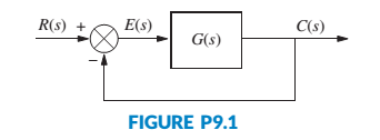
Chapter 9, Problem 25P
For the unity feedback system in Figure P9.1, with
design a PID controller that will yield a peak time of 1.122 seconds and a damping ratio of 0.707, with zero error for a step input. [Section: 9.4]
Expert Solution & Answer
Want to see the full answer?
Check out a sample textbook solution
Students have asked these similar questions
Can you also please do the simulate the step response in MATLAB for the design and report archieved PO and settling time? Thank you.
For a unity negative feedback control system having an open-loop transfer function, G(s) as given
below. Find out the value of "K" such that the system will be in the stable region.
(K/s)
(s3 + 12. 5s2 + 50. 5s + 66)
G(s) =
2.2 Please answer the best you can.
Chapter 9 Solutions
CONTROL SYSTEMS ENGINEERING
Ch. 9 - Prob. 1RQCh. 9 - Name two major advantages of the design techniques...Ch. 9 - What kind of compensation improves the...Ch. 9 - 4. What kind of compensation improves transient...Ch. 9 - 5. What kind of compensation improves both...Ch. 9 - Prob. 6RQCh. 9 - Prob. 7RQCh. 9 - What difference on the s-plane is noted between...Ch. 9 - Prob. 9RQCh. 9 - Why is there more improvement in steady-state...
Ch. 9 - Prob. 11RQCh. 9 - 12. A lag compensator with the zero 25 times as...Ch. 9 - Prob. 13RQCh. 9 - Prob. 14RQCh. 9 - The unity feedback system shown in Figure P9.1...Ch. 9 - Prob. 18PCh. 9 - Prob. 19PCh. 9 - Prob. 22PCh. 9 - For the unity feedback system in Figure P9.1, with...Ch. 9 - Prob. 26PCh. 9 - Prob. 29PCh. 9 - Prob. 31PCh. 9 - Prob. 32PCh. 9 - Prob. 34PCh. 9 - Identify and realize the following compensators...Ch. 9 - Prob. 36PCh. 9 - Prob. 37PCh. 9 - Figure P9.5 shows a two-tank system. The liquid...Ch. 9 - Figure P9.6(a) shows a heat-exchanger process...Ch. 9 - Repeat Problem 39, Parts b and c, using a lead...Ch. 9 - Prob. 41PCh. 9 - 42. You are given the motor whose transfer...Ch. 9 - Prob. 43PCh. 9 - A position control is to be designed with a 10%...Ch. 9 - Prob. 45PCh. 9 - Prob. 46PCh. 9 - Prob. 47PCh. 9 - Repeat Problem 47 using a lag-lead compensator...Ch. 9 - Prob. 51PCh. 9 - A metering pump is a pump capable of delivering a...
Knowledge Booster


Learn more about
Need a deep-dive on the concept behind this application? Look no further. Learn more about this topic, mechanical-engineering and related others by exploring similar questions and additional content below.Similar questions
- and 1) 2) LIUS S Consider the following feedback system, where K is a constant gain G(s) === 1 s3 +382 +s+1 Let K be a real number. Utilize the Routh-Hurwitz criterion to derive stability conditions for the closed-loop system. Suppose that the reference input r(t) = 1. What are the steady-state tracking errors (ess) for K = 1 and K = 3, respectively? R K G(s) Y Figure 2: Control system in Problem 2.arrow_forwardb) Closed-loop transfer function of a unity-feedback system is given by Y(s) / R(s)=1/(ts+1) .Discuss steady-state error for positional, velocity, and acceleration input?arrow_forwardI need answer within 20 minutes please please with my best wishes Husseinarrow_forward
- The open loop transfer function of a unity feedback control system is given below; G(s) = K s(s+2)(s2+2s+2) Plot the root locus and determine the value of k at the break away point.arrow_forwardHand written plzzz...i'll give you multiple upvote..asap...arrow_forwardConsider the plant with transfer function G(s) connected in standard feedback configuration with the controller De(s) = K. 1) 2) = s+2 (s+1)²+1 Sketch the root locus for G(s). Explain what rules you used to plot it. (Be sure to describe the following: the number of branches, where they start and where they are going; the real-axis portion of the root locus; jw-axis crossings (if any); points of multiple roots (if any).) What conditions need to be imposed if we want our closed-loop system to have no oscillations under a step input? Explain the conditions from the root locus. + Ro Σ Dc(s) G(s) Figure 1: Control system in Problem 1.arrow_forward
- A second order plant with unity feedback is cascaded by a proportional controller as shown. If K is 100, 1. HI. Determine its closed-loop poles Y(s)/R(s). Determine its transfer function of E(s)/R(s) Calculate the steady state error of the following block diagram for a unit step R(s) input. iv. Suggest a method to improve on the steady state error. E(s) K pito 7 (s+2)(s+5) Y(s)arrow_forwardblock diagram pls solve fast As Simplify the multiple loop feedback control system? R(s) G₁ G₂ H3 H₂ + G3 H₁ G₁ Y(s)arrow_forward1. Give an example of open loop and closed loop system (one example each). Also state the input, control system, feedback and output parameter. Example. 1. Open Loop - Water Heater: Input - Water Temperature (Cold) System - Heating Element Output - Water Temperature (Hot) 2. Closed Loop - Air-conditioning System Input - Desired Room Temperature Control - Motor controller/Compressor/ACU Feedback - Temperature Sensing Output - Room Temperaturearrow_forward
arrow_back_ios
SEE MORE QUESTIONS
arrow_forward_ios
Recommended textbooks for you
 Understanding Motor ControlsMechanical EngineeringISBN:9781337798686Author:Stephen L. HermanPublisher:Delmar Cengage Learning
Understanding Motor Controls
Mechanical Engineering
ISBN:9781337798686
Author:Stephen L. Herman
Publisher:Delmar Cengage Learning
The Robot Revolution: The New Age of Manufacturing | Moving Upstream; Author: Wall Street Journal;https://www.youtube.com/watch?v=HX6M4QunVmA;License: Standard Youtube License