
Shigley's Mechanical Engineering Design (McGraw-Hill Series in Mechanical Engineering)
10th Edition
ISBN: 9780073398204
Author: Richard G Budynas, Keith J Nisbett
Publisher: McGraw-Hill Education
expand_more
expand_more
format_list_bulleted
Concept explainers
Videos
Textbook Question
Chapter 9, Problem 26P
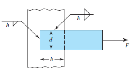
9-25 to 9-28 The weldment shown in the figure is subjected to an alternating force F. The hot-rolled steel bar has a thickness h and is of AISI 1010 steel. The vertical support is likewise AISI 1010 HR steel. The electrode is given in the table below. Estimate the fatigue load F the bar will carry if three fillet welds are used.
| Problem Number | b | d | h | Electrode |
| 9–25 | 50 mm | 50 mm | 5 mm | E6010 |
| 9–26 | 2 in | 2 in |
|
E6010 |
| 9–27 | 50 mm | 30 mm | 5 mm | E7010 |
| 9–28 | 4 in | 2 in |
|
E7010 |
Expert Solution & Answer

Trending nowThis is a popular solution!

Students have asked these similar questions
The carrier plate material St52 (S355) given in the figure below is welded to the body. combined. F1 = 4 kN and F2 = 40 kN static forces act on the plate. Source I. Quality (v2 = 1), no impact (v3 = 1), weld thickness a = 5 mm, safety coefficient s = 2 and weld seam coefficient v1 = 0.8 will be taken. Find out whether a = 5 mm weld seam thickness is sufficient or not, according to the data in the figure and above.
appropriate length of the weld joint shown in the figure if the force is equal to (60000lb) and the operating stress value is (60ksi) and the size of the weld is (1/4in).
(1) What are the methods used to obtain a good weld when welding steel when the carbon content is high? b) Find the appropriate size and length for the weld joint shown in the figure if the strength is equal to (70000Ib) and the allowable shear stress value is 40ksi and the weld rib dimension is (1/4in)
Chapter 9 Solutions
Shigley's Mechanical Engineering Design (McGraw-Hill Series in Mechanical Engineering)
Ch. 9 - 91 to 94 The figure shows a horizontal steel bar...Ch. 9 - 91 to 94 The figure shows a horizontal steel bar...Ch. 9 - 91 to 94 The figure shows a horizontal steel bar...Ch. 9 - 91 to 94 The figure shows a horizontal steel bar...Ch. 9 - 95 to 98 For the weldments of Probs. 91 to 94, the...Ch. 9 - 95 to 98 For the weldments of Probs. 91 to 94, the...Ch. 9 - 95 to 98 For the weldments of Probs. 91 to 94, the...Ch. 9 - 95 to 98 For the weldments of Probs. 91 to 94, the...Ch. 9 - 99 to 912 The materials for the members being...Ch. 9 - Prob. 10P
Ch. 9 - Prob. 11PCh. 9 - 99 to 912 The materials for the members being...Ch. 9 - 913 to 916 A steel bar of thickness h is welded to...Ch. 9 - 913 to 916 A steel bar of thickness h is welded to...Ch. 9 - 913 to 916 A steel bar of thickness h is welded to...Ch. 9 - Prob. 16PCh. 9 - Prob. 17PCh. 9 - 917 to 920 A steel bar of thickness h, to be used...Ch. 9 - 917 to 920 A steel bar of thickness h, to be used...Ch. 9 - 917 to 920 A steel bar of thickness h, to be used...Ch. 9 - Prob. 21PCh. 9 - 921 to 924 The figure shows a weldment just like...Ch. 9 - Prob. 23PCh. 9 - Prob. 24PCh. 9 - 9-25 to 9-28 The weldment shown in the figure is...Ch. 9 - 9-25 to 9-28 The weldment shown in the figure is...Ch. 9 - Prob. 27PCh. 9 - 925 to 928 The weldment shown in the figure is...Ch. 9 - The permissible shear stress for the weldment...Ch. 9 - Prob. 30PCh. 9 - 9-30 to 9-31 A steel bar of thickness h is...Ch. 9 - In the design of weldments in torsion it is...Ch. 9 - Prob. 33PCh. 9 - Prob. 34PCh. 9 - The attachment shown carries a static bending load...Ch. 9 - The attachment in Prob. 935 has not had its length...Ch. 9 - Prob. 37PCh. 9 - Prob. 39PCh. 9 - Prob. 40PCh. 9 - Prob. 42PCh. 9 - 9-43 to 9-45 A 2-in dia. steel bar is subjected to...Ch. 9 - 9-43 to 9-45 A 2-in dia. steel bar is subjected to...Ch. 9 - Prob. 45PCh. 9 - Prob. 46PCh. 9 - Find the maximum shear stress in the throat of the...Ch. 9 - The figure shows a welded steel bracket loaded by...Ch. 9 - Prob. 49PCh. 9 - Prob. 50PCh. 9 - Prob. 51PCh. 9 - Brackets, such as the one shown, are used in...Ch. 9 - For the sake of perspective it is always useful to...Ch. 9 - Hardware stores often sell plastic hooks that can...Ch. 9 - For a balanced double-lap joint cured at room...
Knowledge Booster


Learn more about
Need a deep-dive on the concept behind this application? Look no further. Learn more about this topic, mechanical-engineering and related others by exploring similar questions and additional content below.Similar questions
- The arm in the figure is combined with a rod with a diameter of d=30 mm and a neck (corner) weld of a=5 mm thickness to the rod wall sourced with. The force acting on the arm is F=2 kN. The lengths are L1=L2=100 mm. Joined parts St37-2 (ak=235 N/mm2 ) made of material. Welding is I. Quality and has no impact effect. Check if the source in zone A is safe. Please pay. (S=1.5 V1=0.8)arrow_forwardThe arm in the figure is combined with a rod with a diameter of d=30 mm and a neck (corner) weld with a thickness of a= 5mm to the rod wall.sourced with. The force acting on the arm is F=2 kN. The lengths are L1=L2=100 mm. Joined parts are made of St37-2 (ak=235 N/mm2) material. Welding is I. Quality and has no impact effect. Check if the source in zone A is safe. (S=1.5 V1=0.8)arrow_forwardA beam is supported and loaded as shown in the figure. Data: L = 1000 mm, c = 300 mm, f = 100 mm, D = 100 mm, d = 80 mm. The beam consists of different parts that are welded, and the fillet weld size a is 4 mm. The load q is 2 kN/m, and P = 10 kN. Calculate the maximum stress in the welds.arrow_forward
- A welded joint, as shown in figure below, is subjected to an eccentric load of 2500 N. Find thesize of the weld, if the maximum shear stress in the weld is not to exceed 50 N/mm2arrow_forwardTe - Effective throat thickness well in mm = 6 sin45° Consider the following drawing in which plate 1 is welded onto plate 2 as shown for tensile and shear loading. The plates are fillet welded with a weld thickness of 6 mm as shown for a length of 150 mm. The plates have an ultimate strength of 275 MPa and the welding was done with F70 welding electrodes, which possesses an ultimate strength of 483 MPa. Consider a partial factor of safety of 1.7 for the welded joint and determine the design strength of the weld joint, both in tension (Tdw) and in shear (Vdw) due to the forces acting on it. a) Determine the design strength of the following weld in tension ( ) due to vertical forces. b) Determine the design strength of the weld in shear ( ) due to horizontal forces. Attached pic is shear equation for calculation Tension equation for calculation is: Tdw = FyLwte /Ymwarrow_forwardTwo shafts are welded together by a 6061-T6 aluminum fillet weld. The shafts turn at 300 r/min and the transmitted power is 60 hp. What must be the minimum radius of the plate around which the weld will be made if it has a thickness of 0.5 cm and a safety factor of 10? (Use the table if necessary) Answer: 5.57 cmarrow_forward
- All-round fillet weld with a steel beam weld thickness a=6 mm and weld seam length shown in the figure welded to the steel column. Forces of 2 kN and 3 kN from the beam end in the horizontal and vertical directions, respectively has been applied. The smallest yield strength of the weld material so that the steel structure has a safety of 2.5. Calculate according to von Mises static damage theory ?arrow_forwardA steel pipe weighing 500 kg with a wall thickness of 7.5 mm is placed on the body as shown in the figure. originated. The weld seam is produced with equal forces of 5000 N in two different directions in the directions shown in the figure. drawn in the direction. The welding quality factor is the 2nd quality, ie 0.80, the safety coefficient is 1.85 and the welding flow strength of 225 N / mm2 check the safety of the source (g = 10 m / s2 ) force: 5500 Narrow_forwardQuestion: a) A plate 100 mm wide and 10 mm thick is to be welded to another plate by means of double parallel fillets. The plates are subjected to a static load of 80 kN. Find the length of weld if the permissible shear stress in the weld does not exceed 55MPa. Determine the increase in load carrying capacity if a combination of single transverse double parallel fillet is used the permissible tensile strength of material is 80MPa. b) Draw a neat sketch of double riveted double cover but joint. If 8mm plates with 20 mm diameter rivets having a pitch of 50 mm are joint using double riveted lap joint. The permissible stresses are permissible tensile stress = 120 MPa;Permissible crushing stress= 100 MPa; Permissble shear stess= 150 MPa. Find the strengths and efficiency of joint, taking the strength of the rivet in double shear acoording to the indian boiler standards.arrow_forward
- A plate 100 mm wide and 12.5 mm thick is to be welded to another plate by means of parallel fillet welds. The plates are subjected to a load of 50 kN. Find the length of the weld so that the maximum stress does not exceed 56 MPa. Consider the joint first under static loading and then under fatigue loading.arrow_forwardA cylindrical air-compressor tank with an inside diameter of 50 mm is to be designed to withstand safely a working pressure of 0.86 MPa. Boiler plate with an allowable tensile stress of 76 MPa. All seams will be butt welds with an expected efficiency of 100 percent. a.) Determine the force per lineal mm of longitudinal seam, b.) Determine the required thickness “t” of wall, c.) Determine the unit stress in the circumferential seam.arrow_forwardA rectangular steel plate is welded as a cantilever to a vertical column and supports a single concentrated load P. Determine the weld size if shear stress in the same is not to exceed 140 MPaarrow_forward
arrow_back_ios
SEE MORE QUESTIONS
arrow_forward_ios
Recommended textbooks for you
 Mechanics of Materials (MindTap Course List)Mechanical EngineeringISBN:9781337093347Author:Barry J. Goodno, James M. GerePublisher:Cengage Learning
Mechanics of Materials (MindTap Course List)
Mechanical Engineering
ISBN:9781337093347
Author:Barry J. Goodno, James M. Gere
Publisher:Cengage Learning
Material Properties 101; Author: Real Engineering;https://www.youtube.com/watch?v=BHZALtqAjeM;License: Standard YouTube License, CC-BY