
Shigley's Mechanical Engineering Design (McGraw-Hill Series in Mechanical Engineering)
10th Edition
ISBN: 9780073398204
Author: Richard G Budynas, Keith J Nisbett
Publisher: McGraw-Hill Education
expand_more
expand_more
format_list_bulleted
Videos
Textbook Question
Chapter 9, Problem 29P
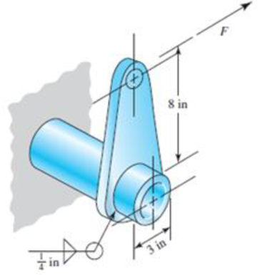
The permissible shear stress for the weldment illustrated is 20 kpsi. Estimate the load, F, that will cause this stress in the weldment throat.
Problem 9–29
Expert Solution & Answer
Want to see the full answer?
Check out a sample textbook solution
Students have asked these similar questions
A bracket is as shown in figure 2. Determine the uniform weld size for the arrangement. The permissible shear stress of weld material is 80 MPa. Consider the loading condition as shown in figure.
A 1/4 in fillet weld is to transmit a total force of 12,000 lb. If the allowable unit stress in shear on the weld is 15,800 psi, the minimum effective length of the weld must be A. 5.4 B 4.9 in C. 4.3 in D 3.9 in.
(1) What are the methods used to obtain a good weld when welding steel when the carbon content is high? b) Find the appropriate size and length for the weld joint shown in the figure if the strength is equal to (70000Ib) and the allowable shear stress value is 40ksi and the weld rib dimension is (1/4in)
Chapter 9 Solutions
Shigley's Mechanical Engineering Design (McGraw-Hill Series in Mechanical Engineering)
Ch. 9 - 91 to 94 The figure shows a horizontal steel bar...Ch. 9 - 91 to 94 The figure shows a horizontal steel bar...Ch. 9 - 91 to 94 The figure shows a horizontal steel bar...Ch. 9 - 91 to 94 The figure shows a horizontal steel bar...Ch. 9 - 95 to 98 For the weldments of Probs. 91 to 94, the...Ch. 9 - 95 to 98 For the weldments of Probs. 91 to 94, the...Ch. 9 - 95 to 98 For the weldments of Probs. 91 to 94, the...Ch. 9 - 95 to 98 For the weldments of Probs. 91 to 94, the...Ch. 9 - 99 to 912 The materials for the members being...Ch. 9 - Prob. 10P
Ch. 9 - Prob. 11PCh. 9 - 99 to 912 The materials for the members being...Ch. 9 - 913 to 916 A steel bar of thickness h is welded to...Ch. 9 - 913 to 916 A steel bar of thickness h is welded to...Ch. 9 - 913 to 916 A steel bar of thickness h is welded to...Ch. 9 - Prob. 16PCh. 9 - Prob. 17PCh. 9 - 917 to 920 A steel bar of thickness h, to be used...Ch. 9 - 917 to 920 A steel bar of thickness h, to be used...Ch. 9 - 917 to 920 A steel bar of thickness h, to be used...Ch. 9 - Prob. 21PCh. 9 - 921 to 924 The figure shows a weldment just like...Ch. 9 - Prob. 23PCh. 9 - Prob. 24PCh. 9 - 9-25 to 9-28 The weldment shown in the figure is...Ch. 9 - 9-25 to 9-28 The weldment shown in the figure is...Ch. 9 - Prob. 27PCh. 9 - 925 to 928 The weldment shown in the figure is...Ch. 9 - The permissible shear stress for the weldment...Ch. 9 - Prob. 30PCh. 9 - 9-30 to 9-31 A steel bar of thickness h is...Ch. 9 - In the design of weldments in torsion it is...Ch. 9 - Prob. 33PCh. 9 - Prob. 34PCh. 9 - The attachment shown carries a static bending load...Ch. 9 - The attachment in Prob. 935 has not had its length...Ch. 9 - Prob. 37PCh. 9 - Prob. 39PCh. 9 - Prob. 40PCh. 9 - Prob. 42PCh. 9 - 9-43 to 9-45 A 2-in dia. steel bar is subjected to...Ch. 9 - 9-43 to 9-45 A 2-in dia. steel bar is subjected to...Ch. 9 - Prob. 45PCh. 9 - Prob. 46PCh. 9 - Find the maximum shear stress in the throat of the...Ch. 9 - The figure shows a welded steel bracket loaded by...Ch. 9 - Prob. 49PCh. 9 - Prob. 50PCh. 9 - Prob. 51PCh. 9 - Brackets, such as the one shown, are used in...Ch. 9 - For the sake of perspective it is always useful to...Ch. 9 - Hardware stores often sell plastic hooks that can...Ch. 9 - For a balanced double-lap joint cured at room...
Knowledge Booster


Learn more about
Need a deep-dive on the concept behind this application? Look no further. Learn more about this topic, mechanical-engineering and related others by exploring similar questions and additional content below.Similar questions
- Two shafts are welded together by a 6061-T6 aluminum fillet weld. The shafts turn at 300 r/min and the transmitted power is 60 hp. What must be the minimum radius of the plate around which the weld will be made if it has a thickness of 0.5 cm and a safety factor of 10? (Use the table if necessary) Answer: 5.57 cmarrow_forwardThe carrier plate material St52 (S355) given in the figure below is welded to the body. combined. F1 = 4 kN and F2 = 40 kN static forces act on the plate. Source I. Quality (v2 = 1), no impact (v3 = 1), weld thickness a = 5 mm, safety coefficient s = 2 and weld seam coefficient v1 = 0.8 will be taken. Find out whether a = 5 mm weld seam thickness is sufficient or not, according to the data in the figure and above.arrow_forwardA rectangular steel plate is welded as a cantilever to a vertical column and supports a single concentrated load P. Determine the weld size if shear stress in the same is not to exceed 140 MPaarrow_forward
- A cylindrical air-compressor tank with an inside diameter of 50 mm is to be designed to withstand safely a working pressure of 0.86 MPa. Boiler plate with an allowable tensile stress of 76 MPa. All seams will be butt welds with an expected efficiency of 100 percent. a.) Determine the force per lineal mm of longitudinal seam, b.) Determine the required thickness “t” of wall, c.) Determine the unit stress in the circumferential seam.arrow_forwardA bracket is welded to the verical column by means of two fillet welds as shown in the figure. Determine the size of the welds, if the permissible shear stress in the weld is limited by 70N/mm^2.arrow_forwardThe allowable unit stress in shear on a fillet weld is 13,600 psi, and the total actual length of the weld cannot exceed 3 in. If the weld must transmit a total force equal to 9600 lb, it’s size should be A. 1/2 in. B. 3/8 in. C. 5/16 in. D. 1/4 in.arrow_forward
- A welded connection has an effective length of 150 mm. 12 mm fillet welds are used. If the ultimate strength of the weld is 485 MPa and its allowable shearing stress is 60% of Fuw. Determine the allowable shearing stress of the weld in MPa.arrow_forwardQuestion No. 11: (a) Illustrate flatness, straightness and circularity with symbol. (b) A circular shaft, 80 mm in diameter is welded to support by means of a circumferential fillet weld. It is subjected to a torsion moment of 3000 N-m. Determine the size of weld, if the maximum shear stress in the weld is not to exceed 70 N/mm2 . (c) Analyze different stresses during design of screw and nutarrow_forwardI need right solution with clear calculations. Two steel plates having yield point stress of 350 N/mm2 are joined together by double fillet welds of 10 mm thick as shown in figure. The weldment is from the same parent plate material. If the weld has to be replaced by 3 bolts of the same material, one each at A and B and one at mid-way between C and D, design the bolts. Take factor of safety as 2 for the boltsarrow_forward
- A tension plate shown below is used to support suspended load "T". Gusset Plate F, = 248 MPa Fu = 400 MPa 200 mm. Determine the allowable tensile capacity of the plate if L= 240 mm. (Assume weld strength is satisfactory)arrow_forwardThe arm in the figure is combined with a rod with a diameter of d=30 mm and a neck (corner) weld of a=5 mm thickness to the rod wall sourced with. The force acting on the arm is F=2 kN. The lengths are L1=L2=100 mm. Joined parts St37-2 (ak=235 N/mm2 ) made of material. Welding is I. Quality and has no impact effect. Check if the source in zone A is safe. Please pay. (S=1.5 V1=0.8)arrow_forwarda) list two advantages and two disadvantages of welded joints b) Name the type of bonding forces applied in welded joints A plate 50mm wide by 11mm thick is joined with another plate 120mm wide by 11mm thick by parallel welds of 40mm long.if the permissible tensile and shear stresses are 110MPa and 80MPa respectively calculate; i) safe load F carried by the joint ii) Efficiency of the jointarrow_forward
arrow_back_ios
SEE MORE QUESTIONS
arrow_forward_ios
Recommended textbooks for you
 Elements Of ElectromagneticsMechanical EngineeringISBN:9780190698614Author:Sadiku, Matthew N. O.Publisher:Oxford University Press
 Mechanics of Materials (10th Edition)Mechanical EngineeringISBN:9780134319650Author:Russell C. HibbelerPublisher:PEARSON
 Thermodynamics: An Engineering ApproachMechanical EngineeringISBN:9781259822674Author:Yunus A. Cengel Dr., Michael A. BolesPublisher:McGraw-Hill Education
 Control Systems EngineeringMechanical EngineeringISBN:9781118170519Author:Norman S. NisePublisher:WILEY
 Mechanics of Materials (MindTap Course List)Mechanical EngineeringISBN:9781337093347Author:Barry J. Goodno, James M. GerePublisher:Cengage Learning
 Engineering Mechanics: StaticsMechanical EngineeringISBN:9781118807330Author:James L. Meriam, L. G. Kraige, J. N. BoltonPublisher:WILEY
Elements Of Electromagnetics
Mechanical Engineering
ISBN:9780190698614
Author:Sadiku, Matthew N. O.
Publisher:Oxford University Press
Mechanics of Materials (10th Edition)
Mechanical Engineering
ISBN:9780134319650
Author:Russell C. Hibbeler
Publisher:PEARSON
Thermodynamics: An Engineering Approach
Mechanical Engineering
ISBN:9781259822674
Author:Yunus A. Cengel Dr., Michael A. Boles
Publisher:McGraw-Hill Education
Control Systems Engineering
Mechanical Engineering
ISBN:9781118170519
Author:Norman S. Nise
Publisher:WILEY
Mechanics of Materials (MindTap Course List)
Mechanical Engineering
ISBN:9781337093347
Author:Barry J. Goodno, James M. Gere
Publisher:Cengage Learning
Engineering Mechanics: Statics
Mechanical Engineering
ISBN:9781118807330
Author:James L. Meriam, L. G. Kraige, J. N. Bolton
Publisher:WILEY
Differences between Temporary Joining and Permanent Joining.; Author: Academic Gain Tutorials;https://www.youtube.com/watch?v=PTr8QZhgXyg;License: Standard Youtube License