
CONNECT F/SHIGLEY'S MECH.ENGR.DESIGN>I<
10th Edition
ISBN: 9781260058499
Author: BUDYNAS
Publisher: INTER MCG
expand_more
expand_more
format_list_bulleted
Concept explainers
Videos
Textbook Question
Chapter 9, Problem 26P
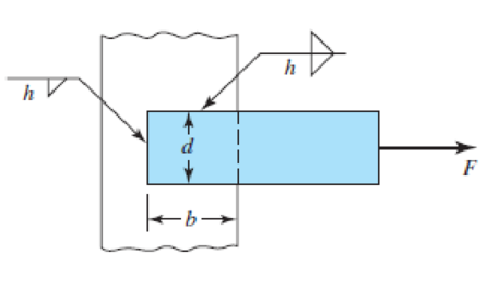
9-25 to 9-28 The weldment shown in the figure is subjected to an alternating force F. The hot-rolled steel bar has a thickness h and is of AISI 1010 steel. The vertical support is likewise AISI 1010 HR steel. The electrode is given in the table below. Estimate the fatigue load F the bar will carry if three fillet welds are used.
| Problem Number | b | d | h | Electrode |
| 9–25 | 50 mm | 50 mm | 5 mm | E6010 |
| 9–26 | 2 in | 2 in |
|
E6010 |
| 9–27 | 50 mm | 30 mm | 5 mm | E7010 |
| 9–28 | 4 in | 2 in |
|
E7010 |
Expert Solution & Answer

Trending nowThis is a popular solution!

Students have asked these similar questions
The weldment shown in the figure is subjected to a force F. The hot-rolled steel bar has
a thickness h and is of AISI 1040 steel. The vertical support is likewise AISI 1040 HR steel.
The electrode is given in the table below. Estimate the static load F the bar can carry if two
fillet welds are used.
b (mm)
h (mm)
d (mm)
70
Elecrode
E8010
30
6
F
Q1: The weldment shown in the figure is subjected to a force F. The hot-rolled steel bar has
a thickness h and is of AISI 1040 steel. The vertical support is likewise AISI 1040 HR steel.
The electrode is given in the table below. Estimate the static load F the bar can carry if two
fillet welds are used.
b (mm)
d (mm)
h (mm)
Elecrode
E8010
30
70
6
ko →→
F
Q1: The weldment shown in the figure is subjected to a force F. The hot-rolled steel bar has
a thickness h and is of AISI 1040 steel. The vertical support is likewise AISI 1040 HR steel.
The electrode is given in the table below. Estimate the static load F the bar can carry if two
fillet welds are used.
b (mm)
h (mm)
d (mm)
70
Elecrode
E8010
30
6
b→→
F
Chapter 9 Solutions
CONNECT F/SHIGLEY'S MECH.ENGR.DESIGN>I<
Ch. 9 - 91 to 94 The figure shows a horizontal steel bar...Ch. 9 - 91 to 94 The figure shows a horizontal steel bar...Ch. 9 - 91 to 94 The figure shows a horizontal steel bar...Ch. 9 - 91 to 94 The figure shows a horizontal steel bar...Ch. 9 - 95 to 98 For the weldments of Probs. 91 to 94, the...Ch. 9 - 95 to 98 For the weldments of Probs. 91 to 94, the...Ch. 9 - 95 to 98 For the weldments of Probs. 91 to 94, the...Ch. 9 - 95 to 98 For the weldments of Probs. 91 to 94, the...Ch. 9 - 99 to 912 The materials for the members being...Ch. 9 - Prob. 10P
Ch. 9 - Prob. 11PCh. 9 - 99 to 912 The materials for the members being...Ch. 9 - 913 to 916 A steel bar of thickness h is welded to...Ch. 9 - 913 to 916 A steel bar of thickness h is welded to...Ch. 9 - 913 to 916 A steel bar of thickness h is welded to...Ch. 9 - Prob. 16PCh. 9 - Prob. 17PCh. 9 - 917 to 920 A steel bar of thickness h, to be used...Ch. 9 - 917 to 920 A steel bar of thickness h, to be used...Ch. 9 - 917 to 920 A steel bar of thickness h, to be used...Ch. 9 - Prob. 21PCh. 9 - 921 to 924 The figure shows a weldment just like...Ch. 9 - Prob. 23PCh. 9 - Prob. 24PCh. 9 - 9-25 to 9-28 The weldment shown in the figure is...Ch. 9 - 9-25 to 9-28 The weldment shown in the figure is...Ch. 9 - Prob. 27PCh. 9 - 925 to 928 The weldment shown in the figure is...Ch. 9 - The permissible shear stress for the weldment...Ch. 9 - Prob. 30PCh. 9 - 9-30 to 9-31 A steel bar of thickness h is...Ch. 9 - In the design of weldments in torsion it is...Ch. 9 - Prob. 33PCh. 9 - Prob. 34PCh. 9 - The attachment shown carries a static bending load...Ch. 9 - The attachment in Prob. 935 has not had its length...Ch. 9 - Prob. 37PCh. 9 - Prob. 39PCh. 9 - Prob. 40PCh. 9 - Prob. 42PCh. 9 - 9-43 to 9-45 A 2-in dia. steel bar is subjected to...Ch. 9 - 9-43 to 9-45 A 2-in dia. steel bar is subjected to...Ch. 9 - Prob. 45PCh. 9 - Prob. 46PCh. 9 - Find the maximum shear stress in the throat of the...Ch. 9 - The figure shows a welded steel bracket loaded by...Ch. 9 - Prob. 49PCh. 9 - Prob. 50PCh. 9 - Prob. 51PCh. 9 - Brackets, such as the one shown, are used in...Ch. 9 - For the sake of perspective it is always useful to...Ch. 9 - Hardware stores often sell plastic hooks that can...Ch. 9 - For a balanced double-lap joint cured at room...
Knowledge Booster


Learn more about
Need a deep-dive on the concept behind this application? Look no further. Learn more about this topic, mechanical-engineering and related others by exploring similar questions and additional content below.Similar questions
- Q1: The weldment shown in the figure is subjected to a force F. The hot-rolled steel bar has a thickness h and is of AISI 1040 steel. The vertical support is likewise AISI 1040 HR steel. The electrode is given in the table below. Estimate the static load F the bar can carry if two fillet welds are used. b (mm) h (mm) d (mm) 70 Elecrode E8010 30 4arrow_forwardQ1: The weldment shown in the figure is subjected to a force F. The hot-rolled steel bar has a thickness and is of AISI 1040 steel. The vertical support is likewise AISI 1040 HR steel. The electrode is given in the table below. Estimate the static load F the bar can carry if two fillet welds are used. h (mm) b (mm) 30 d (mm) 70 Elecrode E8010arrow_forwardQ1: The weldment shown in the figure is subjected to a force F. The hot-rolled steel bar has a thickness h and is of AISI 1040 steel. The vertical support is likewise AISI 1040 HR steel. The electrode is given in the table below. Estimate the static load F the bar can carry if two fillet welds are used. d (mm) h (mm) Elecrode b (mm) 30 70 6 E8010 4 ko →arrow_forward
- The weldment shown in the figure is subjected to a static force of 100 kN. The hot-rolled steel bar has a thickness h=6 mm and is of AISI 1015 HR steel. The vertical support is AISI 1015 HR steel. The electrode is given in the table below. Use the welding code method. (a) is the weld metal strength satisfactory? (b) Is the attachment strength satisfactory? h h=6 mm b=60 mm d=90mm electrode=E6010 |-b- h Farrow_forward9-34 The attachment shown in the figure is made of 1018 HR steel 12 mm thick. The static force is 100 kN. The member is 75 mm wide. Specify the weldment (give the patter, electrode number, type of weld, length of weld, and leg size). 100- 1018 HRV 1018 HR Dimensions in millimeters. 37.5 dia. 75 dia -12 TO 225 F = 100 KN Problem 9-34arrow_forwardThe weldment shown in Figure 2 is subjected to an alternating force F. The hot-rolled steel bar is 10 mm thick and is of AISI 1010 steel. The vertical support is likewise of 1010 steel. The electrode is 6010. (a) Estimate the fatigue load F the bar will carry if three 6-mm fillet welds are used. 6. 6 50 F -60 Dimensions in millimetersarrow_forward
- 8. Design the length of weld (L) in the connection below to develop the full tensile capacity of the plate. Use E70 electrodes and 1/4" side fillet welds. The material is ASTM A36 Steel and the allowable axial tensile stress is 22,000 psi. (show all your work) "L" PL 1/2" PL 3/8" x 6" Parrow_forwardThe arm in the figure is combined with a rod with a diameter of d=30 mm and a neck (corner) weld with a thickness of a= 5mm to the rod wall.sourced with. The force acting on the arm is F=2 kN. The lengths are L1=L2=100 mm. Joined parts are made of St37-2 (ak=235 N/mm2) material. Welding is I. Quality and has no impact effect. Check if the source in zone A is safe. (S=1.5 V1=0.8)arrow_forwardFigure 4 shows a rectangular hollow steel bar welded to a vertical member. The bar has to support a IkN load at its free end. Fillet welds extend all around the outer periphery of the bar. Assuming that the Distortion Energy Theory is applicable, i.e., Say = 0.58 x S, determine the required weld size using a welding rod with S, = 330 MPa and a safety factor of 3 based on yielding. Neglect the weight of the rectangular bar. 1 kN 60 2 25 15 Figure 4 with all dimensions given in millimetresarrow_forward
- A steel pipe weighing 500 kg with a wall thickness of 7.5 mm is placed on the body as shown in the figure. originated. The weld seam is produced with equal forces of 5000 N in two different directions in the directions shown in the figure. drawn in the direction. The welding quality factor is the 2nd quality, ie 0.80, the safety coefficient is 1.85 and the welding flow strength of 225 N / mm2 check the safety of the source (g = 10 m / s2 ) force: 5500 Narrow_forwardThe carrier plate material St52 (S355) given in the figure below is welded to the body. combined. F1 = 4 kN and F2 = 40 kN static forces act on the plate. Source I. Quality (v2 = 1), no impact (v3 = 1), weld thickness a = 5 mm, safety coefficient s = 2 and weld seam coefficient v1 = 0.8 will be taken. Find out whether a = 5 mm weld seam thickness is sufficient or not, according to the data in the figure and above.arrow_forwardappropriate length of the weld joint shown in the figure if the force is equal to (60000lb) and the operating stress value is (60ksi) and the size of the weld is (1/4in).arrow_forward
arrow_back_ios
SEE MORE QUESTIONS
arrow_forward_ios
Recommended textbooks for you
 Elements Of ElectromagneticsMechanical EngineeringISBN:9780190698614Author:Sadiku, Matthew N. O.Publisher:Oxford University Press
 Mechanics of Materials (10th Edition)Mechanical EngineeringISBN:9780134319650Author:Russell C. HibbelerPublisher:PEARSON
 Thermodynamics: An Engineering ApproachMechanical EngineeringISBN:9781259822674Author:Yunus A. Cengel Dr., Michael A. BolesPublisher:McGraw-Hill Education
 Control Systems EngineeringMechanical EngineeringISBN:9781118170519Author:Norman S. NisePublisher:WILEY
 Mechanics of Materials (MindTap Course List)Mechanical EngineeringISBN:9781337093347Author:Barry J. Goodno, James M. GerePublisher:Cengage Learning
 Engineering Mechanics: StaticsMechanical EngineeringISBN:9781118807330Author:James L. Meriam, L. G. Kraige, J. N. BoltonPublisher:WILEY
Elements Of Electromagnetics
Mechanical Engineering
ISBN:9780190698614
Author:Sadiku, Matthew N. O.
Publisher:Oxford University Press
Mechanics of Materials (10th Edition)
Mechanical Engineering
ISBN:9780134319650
Author:Russell C. Hibbeler
Publisher:PEARSON
Thermodynamics: An Engineering Approach
Mechanical Engineering
ISBN:9781259822674
Author:Yunus A. Cengel Dr., Michael A. Boles
Publisher:McGraw-Hill Education
Control Systems Engineering
Mechanical Engineering
ISBN:9781118170519
Author:Norman S. Nise
Publisher:WILEY
Mechanics of Materials (MindTap Course List)
Mechanical Engineering
ISBN:9781337093347
Author:Barry J. Goodno, James M. Gere
Publisher:Cengage Learning
Engineering Mechanics: Statics
Mechanical Engineering
ISBN:9781118807330
Author:James L. Meriam, L. G. Kraige, J. N. Bolton
Publisher:WILEY
Material Properties 101; Author: Real Engineering;https://www.youtube.com/watch?v=BHZALtqAjeM;License: Standard YouTube License, CC-BY