
Videos
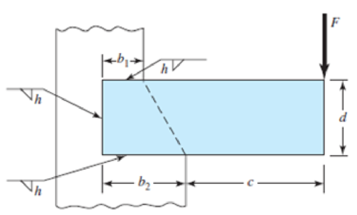
9-30 to 9-31 A steel bar of thickness h is subjected to a bending force F. The vertical support is stepped such that the horizontal welds are b1 and b2 long. Determine F if the maximum allowable shear stress is τallow.
| Problem Number | b1 | b2 | c | d | h | τallow |
| 9–30 | 2 in | 4 in | 6 in | 4 in |
|
25 kpsi |
| 9–31 | 30 mm | 50 mm | 150 mm | 50 mm | 5 mm | 140 MPa |
Problems 9–30 to 9–31
The bending force
Answer to Problem 31P
The bending force
Explanation of Solution
The below figure shows the dimension of the weld.
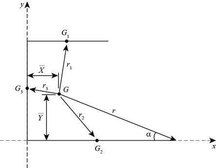
Figure-(1)
Write the expression for throat area of weld-1.
Here, the thickness of weld is
Write the expression for throat area of weld-2.
Here, the length of weld is
Write the expression for throat area of weld-3.
Here, the length of weld is
Write the expression for total throat area.
Write the expression for total length of the weld.
Write the expression for location of centroid along x-direction.
Here, the centroidal length of weld-1 is
Write the expression for centroid along y-direction.
Here, the centroidal distance of weld-1 is
Write the expression for the length between total weld and weld-1.
Write the expression for length between total weld and weld-2.
Write the expression for length of total weld and weld-3.
Write the expression for polar moment of inertia of weld-1 about its centroid.
Write the expression for moment of inertia of weld-2 about its centroid.
Write the expression for polar moment of inertia of weld-3 about its centroid.
Write the expression for polar moment of inertia of the total weld.
Write the expression for length where maximum secondary shear stress occurs.
Write the expression for angle of
Write the expression for moment about weld center.
Here, the load on the weld is
Write the expression for primary shear stress.
Write the expression for secondary shear.
Write the expression for maximum shear stresss.
Conclusion:
Substitute
Substitute
Substitute
Substitute
Substitute
Substitute
Substitute
Substitute
Substitute
Substitute
Substitute
Substitute
Substitute
Substitute
Substitute
Substitute
Substitute
Substitute
Substitute
Substitute
Thus, the bending force is
Want to see more full solutions like this?
Chapter 9 Solutions
Shigley's Mechanical Engineering Design (McGraw-Hill Series in Mechanical Engineering)


- : A cylindrical tank with diameter d = 18 in, is subjected to internal gas pressure p = 450 psi. The tank is constructed of steel sections that arc welded circum fereiitially (sec figure). The heads of the tank are hemispherical. The allowable tensile and shear stresses are 8200 psi and 3000 psi, respectively. Also, the allowable tensile stress perpendicular to a weld is 6250 psi. Determine the minimum required thickness /minof (a) the cylindrical part of the tank and (b) the hemispherical heads.arrow_forwardA tie-down on the deck of a sailboat consists of a bent bar boiled at both ends, as shown in the figure. The diameter dBof the bar is 1/4 in., the diameter D Wof the washers is 7/8 in., and the thickness is of the fiberglass deck is 3/8 in. If the allowable shear stress in the fiberglass is 300 psi, and the allowable bearing pressure between the washer and the fiberglass is 550 psi, what is the allowable load P allowon the tie-down?arrow_forwardA retaining wall (Fig. a) is constructed using steel W-shape columns and concrete panel infill (Fig, b). Each column is subjected to lateral soil pressure with peak intensity q0(Figs, b and c). The tensile and compressive strength of the beam is 600 MPa. Select the most economical W 360 section from Table F-l(b) based on safety factor of 3.0.arrow_forward
- A mountain bike rider going uphill applies a force P = 65 N to each end of the handlebars AB CD, made of aluminum alloy 7075-T6, by pulling on the handlebar extenders (DF on right handlebar segment). Consider the right half of the handlebar assembly only (assume the bars are fixed at the fork at A), Segments AB and CD are prismatic with lengths Lvand L3 and with outer diameters and thicknesses J01, /01 and d03, /03, respectively, as shown. Segment BC of length L2, however, is tapered, and outer diameter and thickness vary linearly between dimensions at B and C Consider shear, torsion, and bending effects only for segment AD; assume DFis rigid. Find the maximum tensile, compressive, and shear stresses adjacent to support A. Show where each maximum stress value occursarrow_forwardA sign for an automobile service station is supported by two aluminum poles of hollow circular cross section, as shown in the figure. The poles are being designed to resist a wind pressure of 75 lb/ft" against the full area of the sign. The dimensions of the poles and sign are hx= 20 ft, /r =5 ft, and h = 10 ft. To prevent buckling of the walls of the poles, the thickness e is specified as one-tenth the outside diameter d. (a) Determine the minimum required diameter of the poles based upon an allowable bending stress of 7500 psi in the aluminum. (b) Determine the minimum required diameter based upon an allowable shear stress of 300 psi.arrow_forwardA 60 mm long and 6 mm thick fillet weld carries a steady load of 15 kN along the weld. The shear strength of the weld material is equal to 200 MPa. The factor of safety is (a) 2.4 (c) 4.8 (b) 3.4 (d) 6.8arrow_forward
- member in a machine is filleted as shown in the figure. The member dimensions are D = 1.300 in, d = 1.000 in, h = 0.125 in, and r = 0.125 in. The member is made of steel with Sut = 45 ksi. The corrected fatigue strength of the member is 30 ksi. Determine the number of life cycles for an alternating stress of 30 ksi. Select one: a. N = 6.99E+04 b. N = 2.56E+04 c. N = 1.66E+05 d. N = 1.00E+06arrow_forwardappropriate length of the weld joint shown in the figure if the force is equal to (60000lb) and the operating stress value is (60ksi) and the size of the weld is (1/4in).arrow_forward9-8kN stress/force on the AB rope holding the base station shown below There are. In order for the net force at point A of this base station to be downward What is the stress/force that should be on the AC rope? A) 5556 N C) 7356 N B) 8200 N D) 3648 N E) 1228 Narrow_forward
- What will be the minimum diameter of a steel wire, which is used to raise a load of 4000N if the stress in the rod is not to exceed 95 MN/m²?arrow_forward1. A solid square rod is cantilevered at one end. The rod is 0.8 m long and supports a completely reversing transverse load at the other end of 50 kN. The material is AISI 1060 hot-rolled steel (?? =370 MPa,?? =680 MPa ). Use a design factor of 2 and determine the dimensions of the square cross section for the following cases. Neglect any stress concentration. a. The rod must support this load for 100 cycles. b. The rod must support this load for 104 cycles. c. The rod must have infinite life.arrow_forwardCalculate the maximum stress in the steel ring if a copper ring with a thread diameter of 2000 mm and a thickness of 20 mm and a steel ring with an inner diameter of 2000 mm and a thickness of 10 mm are interlocked and heated to 100°C. Scale= 100 GPa, Eçelik= 200 GPa, copper= 16.106/°C, steel= 12.10-6/°C a-) 20 MPa b-) 40 MPa c-) 50MPa d-) 60 MPa e-) 30 MPaarrow_forward
 Mechanics of Materials (MindTap Course List)Mechanical EngineeringISBN:9781337093347Author:Barry J. Goodno, James M. GerePublisher:Cengage Learning