
EBK STATICS AND MECHANICS OF MATERIALS
5th Edition
ISBN: 8220102955295
Author: HIBBELER
Publisher: PEARSON
expand_more
expand_more
format_list_bulleted
Videos
Textbook Question
Chapter 9.2, Problem 16P
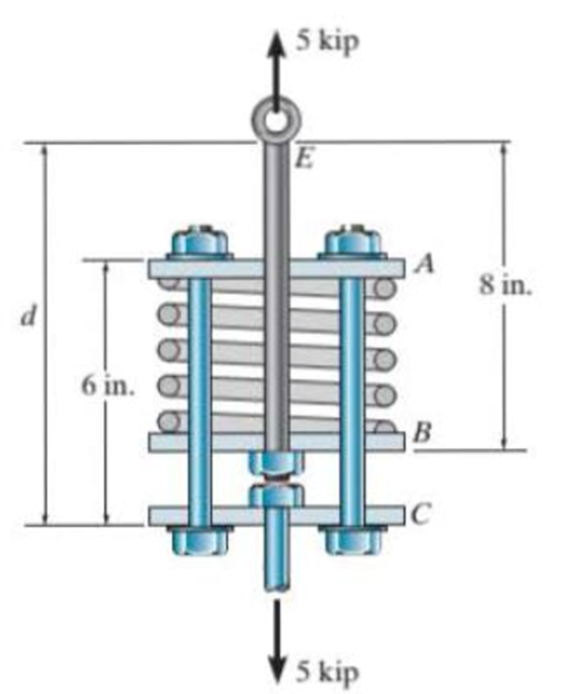
The coupling rod is subjected to a force of 5 kip. Determine the distance d between C and E accounting for the compression of the spring and the deformation of the bolts. When no load is applied the spring is unstretched and d = 10 in. The material is A-36 steel and each bolt has a diameter of 0.25 in. The plates at A, B, and C are rigid and the spring has a stiffness of k = 12 kip/in.
Prob. 9-16
Expert Solution & Answer
Want to see the full answer?
Check out a sample textbook solution
Students have asked these similar questions
The pipe is stuck in the ground so that when it is pulled upward the frictional force along its length varies linearly from zero at B to fmax (force/length) at C. Determine the initial force P required to pull the pipe out and the pipe’s elongation just before it starts to slip. The pipe has a length L, cross-sectional area A, and the material from which it is made has a modulus of elasticity E.
The bracket is held to the wall using three A-36 steel bolts at B, C, and D. Each bolt has a diameter of 0.5 in. and an unstretched length of 2 in. If a force of 800 lb is placed on the bracket as shown, determine how far, s, the top bracket at bolt D moves away from the wall. For the calculation, assume that the bolts carry no shear; rather, the vertical force of 800 lb is supported by the toe at A. Also, assume that the wall and bracket are rigid. A greatly exaggerated deformation of the bolts is shown.
The plastic 50-mm diameter rod is placed in a 51-mm-diameter hole with rigid walls. Determine the change in the length of the rod after the 8 kN load is applied. Use E = 40 MPa and v=0.45 for the rod.
Chapter 9 Solutions
EBK STATICS AND MECHANICS OF MATERIALS
Ch. 9.2 - In each case, determine the internal normal force...Ch. 9.2 - Determine the internal normal force between...Ch. 9.2 - The post weighs 8 kN/m. Determine the internal...Ch. 9.2 - The rod is subjected to an external axial force of...Ch. 9.2 - The rigid beam supports the load of 60 kN....Ch. 9.2 - The 20-mm-diameter A-36 steel rod is subjected to...Ch. 9.2 - Prob. 2FPCh. 9.2 - The 30-mm-diameter A992 steel rod is subjected to...Ch. 9.2 - Prob. 4FPCh. 9.2 - Prob. 5FP
Ch. 9.2 - The 20-mm-diameter 2014-T6 aluminum rod is...Ch. 9.2 - The A992 steel rod is subjected to the loading...Ch. 9.2 - The copper shaft is subjected to the axial loads...Ch. 9.2 - The composite shaft, consisting of aluminum,...Ch. 9.2 - The composite shaft, consisting of aluminum,...Ch. 9.2 - The 2014-T6 aluminum rod has a diameter of 30 mm...Ch. 9.2 - The A-36 steel drill shaft of an oil well extends...Ch. 9.2 - The truss is made of three A-36 steel members,...Ch. 9.2 - The truss is made of three A-36 steel members,...Ch. 9.2 - The assembly consists of two 10-mm diameter red...Ch. 9.2 - The assembly consists of two 10-mm diameter red...Ch. 9.2 - The load is supported by the four 304 stainless...Ch. 9.2 - The load is supported by the four 304 stainless...Ch. 9.2 - The rigid bur is supported by the pin-connected...Ch. 9.2 - The post is made of Douglas fir and has a diameter...Ch. 9.2 - The post is made of Douglas fir and has a diameter...Ch. 9.2 - The coupling rod is subjected to a force of 5 kip....Ch. 9.2 - Prob. 17PCh. 9.2 - The linkage is made of three pin-connected A992...Ch. 9.2 - The linkage is made of three pin-connected A992...Ch. 9.2 - The assembly consists of three titanium...Ch. 9.2 - The rigid beam is supported at its ends by two...Ch. 9.2 - Prob. 22PCh. 9.2 - The steel bar has the original dimensions shown in...Ch. 9.2 - Determine the relative displacement of one end of...Ch. 9.2 - Prob. 25PCh. 9.2 - The truss consists of three members, each made...Ch. 9.2 - Prob. 27PCh. 9.2 - The observation cage C has a weight of 250 kip and...Ch. 9.2 - Determine the elongation of the aluminum strap...Ch. 9.2 - The ball is truncated at its ends and is used to...Ch. 9.5 - The column is constructed from high-strength...Ch. 9.5 - The column is constructed from high-strength...Ch. 9.5 - The A-36 steel pipe has a 6061-T6 aluminum core....Ch. 9.5 - If column AB is made from high strength precast...Ch. 9.5 - If column AB is made from high strength precast...Ch. 9.5 - Determine the support reactions at the rigid...Ch. 9.5 - If the supports at A and C are flexible and have a...Ch. 9.5 - The load of 2000 lb is to be supported by the two...Ch. 9.5 - The load of 2000 lb is to be supported by the two...Ch. 9.5 - The A-36 steel pipe has an outer radius of 20 mm...Ch. 9.5 - The 10-mm-diameter steel bolt is surrounded by a...Ch. 9.5 - The 10-mm-diametcr steel bolt is surrounded by a...Ch. 9.5 - The assembly consists of two red brass C83400...Ch. 9.5 - The rigid beam is supported by the three suspender...Ch. 9.5 - Prob. 45PCh. 9.5 - If the gap between C and the rigid wall at D is...Ch. 9.5 - The support consists of a solid red brass C83400...Ch. 9.5 - The specimen represents a filament-reinforced...Ch. 9.5 - The rigid bar is pinned at A and supported by two...Ch. 9.5 - The rigid bar is pinned at A and supported by two...Ch. 9.5 - The rigid bar is pinned at A and supported by two...Ch. 9.5 - The rigid bar is pinned at A and supported by two...Ch. 9.5 - The 2014-T6 aluminum rod AC is reinforced with the...Ch. 9.5 - The 2014-T6 aluminum rod AC is reinforced with the...Ch. 9.5 - The three suspender bars are made of A992 steel...Ch. 9.6 - The C83400-red-brass rod AB and 2014-T6-aluminum...Ch. 9.6 - The assembly has the diameters and material...Ch. 9.6 - The rod is made of A992 steel and has a diameter...Ch. 9.6 - The two cylindrical rod segments are fixed to the...Ch. 9.6 - The two cylindrical rod segments are fixed to the...Ch. 9.6 - Prob. 61PCh. 9.6 - The bronze C86100 pipe has an inner radius of 0.5...Ch. 9.6 - The 40-ft-long A-36 steel rails on a train track...Ch. 9.6 - The device is used to measure a change in...Ch. 9.6 - Prob. 65PCh. 9.6 - Prob. 66PCh. 9.6 - Prob. 67PCh. 9.6 - When the temperature is at 30C, the A-36 steel...Ch. 9.6 - The 50-mm-diameter cylinder is made from Am...Ch. 9.6 - The 50-mm-diametcr cylinder is made from Am...Ch. 9.6 - Prob. 71PCh. 9.6 - The cylinder CD of the assembly is heated from T1...Ch. 9.6 - The cylinder CD of the assembly is heated from T1...Ch. 9.6 - Prob. 74PCh. 9 - The assembly consists of two A992 steel bolts AB...Ch. 9 - The assembly shown consists of two A992 steel...Ch. 9 - The rods each have the same 25-mm diameter and...Ch. 9 - Two A992 steel pipes, each having a...Ch. 9 - The 2014-T6 aluminum rod has a diameter of 0.5 in....Ch. 9 - The 2014-T6 aluminum rod has a diameter of 0.5 in....Ch. 9 - The rigid link is supported by a pin at A and two...Ch. 9 - The joint is made from three A992 steel plates...
Knowledge Booster


Learn more about
Need a deep-dive on the concept behind this application? Look no further. Learn more about this topic, mechanical-engineering and related others by exploring similar questions and additional content below.Similar questions
- Before the load is placed on the rigid plate, the top of the central spring is 20 mm lower than the outer springs. Each outer spring is made of 24 turns of 15-mm diameter wire on a mean radius of 60 mm. The central spring consists of 16 turns of 20 mm dimeter wire on a mean radius of 80 mm. If a load P = 5 kN is now placed on the rigid plate. Disregarding the weight of the plate, use G = 83 GPa and use Light spring formula. Determine the maximum shearing stress of the in uter spring. In MPaarrow_forwardThe rigid beam is supported by the three posts A, B, and C. Posts A and C have a diameter of 60 mm and are made of a material for which E = 70 GPa and sY = 20 MPa. Post B is made of a material for which E = 100 GPa andsY = 590 MPa. If P = 130 kN, determine the diameter of post B so that all three posts are about to yield.arrow_forwardThe spring has a stiffness of k = 800 N/m and an unstretched length of 200 mm. Determine the force in cables BC and BD when the spring is held in the position shown. 400 mm A k= 800 N/m gram (FBD) a tana =1 45* 4 a = 45° 300 mm 500 mm -400 mm- quilibriumarrow_forward
- The rigid lever arm is supported by two A-36 steel wires having the same diameter of 4 mm. If a force of P = 3 kN is applied to the handle, determine the force developed in both wires and their corresponding elongations. Consider A-36 steel as an elastic perfectly plastic material.arrow_forwardThe post is made of Douglas fir and has a diameter of 100 mm. If it is subjected to the load of 20 kN and the soil provides a frictional resistance that is distributed along its length and varies linearly from w = 4 kN>m at y = 0 to w = 12 kN>m at y = 2 m, determine the force F at its bottom needed for equilibrium. Also, what is the displacement of the top of the post A with respect to its bottom B? Neglect the weight of the post.arrow_forwardThe bracket is held to the wall using three A-36 steel bolts at B, C, and D. Each bolt has a diameter of 0.5 in. and an unstretched length of 2 in. If a force of 800 lb is placed on the bracket as shown,determine the force developed in each bolt. For the calculation, assume that the bolts carry no shear; rather, the vertical force of 800 lb is supported by the toe at A. Also, assume that the wall and bracket are rigid. A greatly exaggerated deformation of the bolts is shown.arrow_forward
- The bracket is held to the wall using three A-36 steel bolts at B, C, and D. Each bolt has a diameter of 0.5 in. and an unstretched length of 2 in. If a force of 800 lb is placed on the bracket as shown, determine the force developed in each bolt. For the calculation, assume that the bolts carry no shear; rather, the vertical force of 800 lb is supported by the toe at A. Also, assume that the wall and bracket are rigid. A greatly exaggerated deformation of the bolts is shown.arrow_forwardA 4-14. The post is made of Douglas fir and has a diameter of 60 mm. If it is subjected to the load of 20 kN and the soil provides a frictional resistance that is uniformly distributed along its sides of w = 4 kN/m, determine the force F at its 20 kN bottom needed for equilibrium. Also, what is the displacement of the top of the post A with respect to its bottom B? Neglect the weight of the post. 4-19. The assembly consists of two A-36 steel rods and a rigid bar BD. Each rod has f10k unliad to thaarrow_forwardThe pipe is stuck in the ground so that when it is pulled upward the frictional force along its length varies linearly from zero at B to fmax (force/length) at C. The pipe has a length L, cross-sectional area A, and the material from which it is made has a modulus of elasticity E. Determine the initial force P required to pull the pipe out. Express your answer as an expression in terms of the variables f, L, A and E and any necessary constants.arrow_forward
- The assembly is used to support the 130-kg container having a center of mass at G. The spring has an unstretched length of 250 mm and stiffness of k = 300 kN/m. (Figure 1). Figure 3 m B Part C 2 m 0 2 m 1 of 1 μĂ Part A NB = 1765.8 Determine the heighth of the spring. Express your answer to three significant figures and include the appropriate units. h = 246 mm Submit ✓ Correct Correct answer is shown. Your answer 246.076 mm was either rounded differently or used a different number of significant figures than required for this part. Part B Previous Answers Determine the reaction at the roller A. Express your answer to three significant figures and include the appropriate units. μА NA = 2501.55 Determine the reaction at the roller B. Express your answer to three significant figures and include the appropriate units. Submit Previous Answers Request Answer N N X Incorrect; Try Again; 3 attempts remaining = ? Submit Previous Answers Request Answer X Incorrect; Try Again; 5 attempts…arrow_forwardThe 10-mm-diameter bolt is made of an aluminum alloy. It fits through a magnesium sleeve that has an inner diameter of 15 mm and an outer diameter of 25 mm. The original lengths of the bolt and sleeve are 80 mm and 50 mm, respectively. If after the nut on the bolt is tightened the tension in the bolt is 10 kN, determine the change in dimension of the cross-section of the bolt and the sleeve. Assume the material at A is rigid. E = 70 GPa, Emg = 45 GPa, Ga = 26 GPa, Gmg = 17 GPa.arrow_forwardCDEFGH is plate with a circular hole in it and has a unit weight p = 2 kN/m². If the initial length of the spring is 1m, find the stretched length of the spring attached at C to the given system. The stiffness of the spring id k=50 kN/m. bwwwww.. 2 m H 0 D X 2 m 2 m G 2 m F E 3m 1marrow_forward
arrow_back_ios
SEE MORE QUESTIONS
arrow_forward_ios
Recommended textbooks for you
 Elements Of ElectromagneticsMechanical EngineeringISBN:9780190698614Author:Sadiku, Matthew N. O.Publisher:Oxford University Press
 Mechanics of Materials (10th Edition)Mechanical EngineeringISBN:9780134319650Author:Russell C. HibbelerPublisher:PEARSON
 Thermodynamics: An Engineering ApproachMechanical EngineeringISBN:9781259822674Author:Yunus A. Cengel Dr., Michael A. BolesPublisher:McGraw-Hill Education
 Control Systems EngineeringMechanical EngineeringISBN:9781118170519Author:Norman S. NisePublisher:WILEY
 Mechanics of Materials (MindTap Course List)Mechanical EngineeringISBN:9781337093347Author:Barry J. Goodno, James M. GerePublisher:Cengage Learning
 Engineering Mechanics: StaticsMechanical EngineeringISBN:9781118807330Author:James L. Meriam, L. G. Kraige, J. N. BoltonPublisher:WILEY
Elements Of Electromagnetics
Mechanical Engineering
ISBN:9780190698614
Author:Sadiku, Matthew N. O.
Publisher:Oxford University Press
Mechanics of Materials (10th Edition)
Mechanical Engineering
ISBN:9780134319650
Author:Russell C. Hibbeler
Publisher:PEARSON
Thermodynamics: An Engineering Approach
Mechanical Engineering
ISBN:9781259822674
Author:Yunus A. Cengel Dr., Michael A. Boles
Publisher:McGraw-Hill Education
Control Systems Engineering
Mechanical Engineering
ISBN:9781118170519
Author:Norman S. Nise
Publisher:WILEY
Mechanics of Materials (MindTap Course List)
Mechanical Engineering
ISBN:9781337093347
Author:Barry J. Goodno, James M. Gere
Publisher:Cengage Learning
Engineering Mechanics: Statics
Mechanical Engineering
ISBN:9781118807330
Author:James L. Meriam, L. G. Kraige, J. N. Bolton
Publisher:WILEY
Mechanical SPRING DESIGN Strategy and Restrictions in Under 15 Minutes!; Author: Less Boring Lectures;https://www.youtube.com/watch?v=dsWQrzfQt3s;License: Standard Youtube License