
EBK STATICS AND MECHANICS OF MATERIALS
5th Edition
ISBN: 8220102955295
Author: HIBBELER
Publisher: PEARSON
expand_more
expand_more
format_list_bulleted
Videos
Textbook Question
Chapter 9.2, Problem 3P
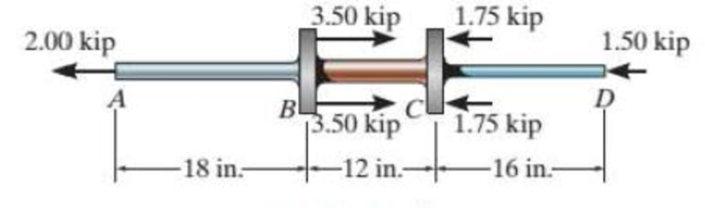
The composite shaft, consisting of aluminum, copper, and steel sections, is subjected to the loading shown. Determine the displacement of end A with respect to end D and the normal stress in each section. The cross-sectional area and modulus of elasticity for each section are shown in the figure. Neglect the size of the collars at B and C.
| Aluminum | Copper | Steel |
| Eal = 10(103) ksi | Ecu = 18(103) ksi | Est =29(103) ksi |
| AAB = 0.09 in2 | ABC = 0.12 in2 | ACD = 0.06 in2 |
Probs. 9-3/4
Expert Solution & Answer
Want to see the full answer?
Check out a sample textbook solution
Students have asked these similar questions
1.
The composite shaft, consisting of aluminum, copper,
and steel sections, is subjected to the loading shown.
Determine the displacement of B with respect to C and the
normal stress in each section. The cross-sectional area and
modulus of elasticity for each section are shown in the figure.
Neglect the size of the collars at B and C.
Aluminum
Eal = 70 GPa
AAB = 58 mm²
9 kN
A
Copper
Ecu = 126 GPa
ABC = 77 mm²
450 mm
16 kN
斤。
16 kN
-300 mm
BL
Steel
Est = 200 GPa
ACD = 39 mm²
8 kN
8 kN
-400 mm
7 kN
4.3 The composite shaft, consisting of aluminum, copper, and steel sections, is subjected to the loading
shown. Determine the displacement of end A with respect to end D and the normal stress in each
section. The cross-sectional area and modulus of elasticity for each section are shown in the figure.
Neglect the size of the collars at Band C.
3.50 kip
1.75 kip
1.50 kip
2.00 kip
Steel
BL
3.50 kip
1.75 kip
Aluminum
Copper
Est = 29 (10)³ Ksi
-18 in-
-12 in-
-16 in-
Ecu = 18 (10)3 Ksi
ABC = 0.12 in?
Eal = 10(10)³ Ksi
AcD = 0.09 6in²
= 0.09 in?
AAB
Question 1
Determine the maximum stresses in
the stepped shaft composite of two
materials steel and Aluminum that
fixed at the two ends as shown in
Figure. It is subjected to a torque of
300 N.m at the section C. The larger
section is of Aluminum and the
smaller one is of steel. Gs = 82 GPa
and Gal = 27 GPa. *
%3D
150
B
D
St
Al
50
300 N.m
600
- 500 –
1 Add file
Chapter 9 Solutions
EBK STATICS AND MECHANICS OF MATERIALS
Ch. 9.2 - In each case, determine the internal normal force...Ch. 9.2 - Determine the internal normal force between...Ch. 9.2 - The post weighs 8 kN/m. Determine the internal...Ch. 9.2 - The rod is subjected to an external axial force of...Ch. 9.2 - The rigid beam supports the load of 60 kN....Ch. 9.2 - The 20-mm-diameter A-36 steel rod is subjected to...Ch. 9.2 - Prob. 2FPCh. 9.2 - The 30-mm-diameter A992 steel rod is subjected to...Ch. 9.2 - Prob. 4FPCh. 9.2 - Prob. 5FP
Ch. 9.2 - The 20-mm-diameter 2014-T6 aluminum rod is...Ch. 9.2 - The A992 steel rod is subjected to the loading...Ch. 9.2 - The copper shaft is subjected to the axial loads...Ch. 9.2 - The composite shaft, consisting of aluminum,...Ch. 9.2 - The composite shaft, consisting of aluminum,...Ch. 9.2 - The 2014-T6 aluminum rod has a diameter of 30 mm...Ch. 9.2 - The A-36 steel drill shaft of an oil well extends...Ch. 9.2 - The truss is made of three A-36 steel members,...Ch. 9.2 - The truss is made of three A-36 steel members,...Ch. 9.2 - The assembly consists of two 10-mm diameter red...Ch. 9.2 - The assembly consists of two 10-mm diameter red...Ch. 9.2 - The load is supported by the four 304 stainless...Ch. 9.2 - The load is supported by the four 304 stainless...Ch. 9.2 - The rigid bur is supported by the pin-connected...Ch. 9.2 - The post is made of Douglas fir and has a diameter...Ch. 9.2 - The post is made of Douglas fir and has a diameter...Ch. 9.2 - The coupling rod is subjected to a force of 5 kip....Ch. 9.2 - Prob. 17PCh. 9.2 - The linkage is made of three pin-connected A992...Ch. 9.2 - The linkage is made of three pin-connected A992...Ch. 9.2 - The assembly consists of three titanium...Ch. 9.2 - The rigid beam is supported at its ends by two...Ch. 9.2 - Prob. 22PCh. 9.2 - The steel bar has the original dimensions shown in...Ch. 9.2 - Determine the relative displacement of one end of...Ch. 9.2 - Prob. 25PCh. 9.2 - The truss consists of three members, each made...Ch. 9.2 - Prob. 27PCh. 9.2 - The observation cage C has a weight of 250 kip and...Ch. 9.2 - Determine the elongation of the aluminum strap...Ch. 9.2 - The ball is truncated at its ends and is used to...Ch. 9.5 - The column is constructed from high-strength...Ch. 9.5 - The column is constructed from high-strength...Ch. 9.5 - The A-36 steel pipe has a 6061-T6 aluminum core....Ch. 9.5 - If column AB is made from high strength precast...Ch. 9.5 - If column AB is made from high strength precast...Ch. 9.5 - Determine the support reactions at the rigid...Ch. 9.5 - If the supports at A and C are flexible and have a...Ch. 9.5 - The load of 2000 lb is to be supported by the two...Ch. 9.5 - The load of 2000 lb is to be supported by the two...Ch. 9.5 - The A-36 steel pipe has an outer radius of 20 mm...Ch. 9.5 - The 10-mm-diameter steel bolt is surrounded by a...Ch. 9.5 - The 10-mm-diametcr steel bolt is surrounded by a...Ch. 9.5 - The assembly consists of two red brass C83400...Ch. 9.5 - The rigid beam is supported by the three suspender...Ch. 9.5 - Prob. 45PCh. 9.5 - If the gap between C and the rigid wall at D is...Ch. 9.5 - The support consists of a solid red brass C83400...Ch. 9.5 - The specimen represents a filament-reinforced...Ch. 9.5 - The rigid bar is pinned at A and supported by two...Ch. 9.5 - The rigid bar is pinned at A and supported by two...Ch. 9.5 - The rigid bar is pinned at A and supported by two...Ch. 9.5 - The rigid bar is pinned at A and supported by two...Ch. 9.5 - The 2014-T6 aluminum rod AC is reinforced with the...Ch. 9.5 - The 2014-T6 aluminum rod AC is reinforced with the...Ch. 9.5 - The three suspender bars are made of A992 steel...Ch. 9.6 - The C83400-red-brass rod AB and 2014-T6-aluminum...Ch. 9.6 - The assembly has the diameters and material...Ch. 9.6 - The rod is made of A992 steel and has a diameter...Ch. 9.6 - The two cylindrical rod segments are fixed to the...Ch. 9.6 - The two cylindrical rod segments are fixed to the...Ch. 9.6 - Prob. 61PCh. 9.6 - The bronze C86100 pipe has an inner radius of 0.5...Ch. 9.6 - The 40-ft-long A-36 steel rails on a train track...Ch. 9.6 - The device is used to measure a change in...Ch. 9.6 - Prob. 65PCh. 9.6 - Prob. 66PCh. 9.6 - Prob. 67PCh. 9.6 - When the temperature is at 30C, the A-36 steel...Ch. 9.6 - The 50-mm-diameter cylinder is made from Am...Ch. 9.6 - The 50-mm-diametcr cylinder is made from Am...Ch. 9.6 - Prob. 71PCh. 9.6 - The cylinder CD of the assembly is heated from T1...Ch. 9.6 - The cylinder CD of the assembly is heated from T1...Ch. 9.6 - Prob. 74PCh. 9 - The assembly consists of two A992 steel bolts AB...Ch. 9 - The assembly shown consists of two A992 steel...Ch. 9 - The rods each have the same 25-mm diameter and...Ch. 9 - Two A992 steel pipes, each having a...Ch. 9 - The 2014-T6 aluminum rod has a diameter of 0.5 in....Ch. 9 - The 2014-T6 aluminum rod has a diameter of 0.5 in....Ch. 9 - The rigid link is supported by a pin at A and two...Ch. 9 - The joint is made from three A992 steel plates...
Knowledge Booster


Learn more about
Need a deep-dive on the concept behind this application? Look no further. Learn more about this topic, mechanical-engineering and related others by exploring similar questions and additional content below.Similar questions
- A thin-walled rectangular tube has uniform thickness t and dimensions a x b to the median line of the cross section (see figure). How does the shear stress in the tube vary with the ratio = a/b if the total length Lmof the median line of the cross section and the torque T remain constant? From your results, show that the shear stress is smallest when the tube is square (ß = 1).arrow_forwardA vertical pole consisting of a circular tube of outer diameter 5 in. and inner diameter 4.5 in. is loaded by a linearly varying distributed force with maximum intensity of q0, Find the maximum shear stress in the pole.arrow_forward, Solve the preceding problem using the numerical data: /) = 90mm, h = 280 mm, d = 210 mm, q = 14 kN/m, and L = L2 m.arrow_forward
- The Z-section of Example D-7 is subjected to M = 5 kN · m, as shown. Determine the orientation of the neutral axis and calculate the maximum tensile stress c1and maximum compressive stress ocin the beam. Use the following numerical data: height; = 200 mm, width ft = 90 mm, constant thickness a = 15 mm, and B = 19.2e. Use = 32.6 × 106 mm4 and I2= 2.4 × 10e mm4 from Example D-7arrow_forwardA pole is fixed at the base and is subjected to a linearly varying distributed force with maximum intensity of q0and an axial compressive load P = 20 kips at the top (see figure). The pole has a circular cross section with an outer diameter of 5 in. and an inner diameter of 4.5 in. Find the normal stresses on the surface of the pole at the base at locations A and B.arrow_forwardA circular post, a rectangular post, and a post of cruciform cross section are each compressed by loads that produce a resultant force P acting at the edge of the cross section (see figure). The diameter of the circular post and the depths of the rectangular and cruciform posts are the same. For what width b of the rectangular post will the maximum tensile stresses be the same in the circular and rectangular posts? Repeat part (a) for the post with cruciform cross section. Under the conditions described in parts (a) and (b), which post has the largest compressive stress?arrow_forward
- An aluminum pole for a street light weighs 4600 N and supports an arm that weighs 660 N (see figure). The center of gravity of the arm is 1.2 m from the axis of the pole, A wind force of 300 N also acts in the (y) direction at 9 m above the base. The outside diameter of the pole (at its base) is 225 mm, and its thickness is 18 mm. Determine the maximum tensile and compressive stresses o, and e1., respectively, in the pole (at its base) due to the weights and the wind force.arrow_forwardRepeat the previous problem using ? = 50° and stresses on the rotated element: sy1= 70 MPa, ??y1=-82 MPa, and tx1y1=-35 MPa.arrow_forwardA sign is supported by a pipe (see figure) having an outer diameter 110 mm and inner diameter 90 mm. The dimensions of the sign are 2.0 m X 1.0 m, and its lower edge is 3.0 m above the base. Note that the center of gravity of the sign is 1.05 m from the axis of the pipe. The wind pressure against the sign is 1.5 kPa. Determine the maximum in-plane shear stresses due to the wind pressure on the sign at points /I, B, and C, located on the outer surface at the base of the pipe.arrow_forward
- The shear stresses t in a rectangular beam arc given by Eq. (5-43): in which Fis the shear force, / is the moment of inertia of the cross-sectional area, /lis the height of the beam, and i] is the distance from the neutral axis to the point where the shear stress is being determined (Fig. 5-32). By integrating over the cross-sectional area, show that the resultant of the shear stresses is equal to the shear force V.arrow_forwardSolve the preceding problem (W 250 × 44.8) if the resultant force P equals 110 kN and E = 200 GPa.arrow_forwardThe state of stress on an element along the hydraulic lift cylinder on a truck is trv= — 5 MPaLFind the maximum shear stress on the clement and show the state of stress on a sketch of a properly oriented clement.arrow_forward
arrow_back_ios
SEE MORE QUESTIONS
arrow_forward_ios
Recommended textbooks for you
 Mechanics of Materials (MindTap Course List)Mechanical EngineeringISBN:9781337093347Author:Barry J. Goodno, James M. GerePublisher:Cengage Learning
Mechanics of Materials (MindTap Course List)
Mechanical Engineering
ISBN:9781337093347
Author:Barry J. Goodno, James M. Gere
Publisher:Cengage Learning
Everything About TRANSVERSE SHEAR in 10 Minutes!! - Mechanics of Materials; Author: Less Boring Lectures;https://www.youtube.com/watch?v=4x0E9yvzfCM;License: Standard Youtube License