
EBK STATICS AND MECHANICS OF MATERIALS
5th Edition
ISBN: 8220102955295
Author: HIBBELER
Publisher: PEARSON
expand_more
expand_more
format_list_bulleted
Videos
Textbook Question
Chapter 9.6, Problem 70P
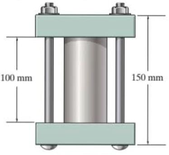
The 50-mm-diametcr cylinder is made from Am 1004-T61 magnesium and is placed in the clamp when the temperature is T1 = 15°C. If the two 304-stainless-steel carriage bolts of the clamp each have a diameter of 10 mm, and they hold the cylinder snug with negligible force against the rigid jaws, determine the temperature at which the average normal stress in either the magnesium or the steel first becomes 12 MPa.
Probs. 9-69/70
Expert Solution & Answer
Want to see the full answer?
Check out a sample textbook solution
Students have asked these similar questions
The 50-mm-diameter cylinder is made from Am 1004-T61 magnesium and is placed in the clamp when the temperature is T1 = 20° C. If the 304-stainless-steel carriage bolts of the clamp each have a diameter of 10 mm, and they hold the cylinder snug with negligible force against the rigid jaws, determine the force in the cylinder when the temperature rises to T2 = 130°C.
The 50-mm-diameter cylinder is made from Am 1004-T61 magnesium and is placed in the clamp
when the temperature is T = 15° C.
(Figure 1)
Part A
If the two 304-stainless-steel carriage bolts of the clamp each have a diameter of 10 mm, and they hold the cylinder snug with negligible force against the rigid jaws, determine the temperature at which the average normal stress in
either the magnesium or the steel first becomes 14.5 MPa
Express your answer to three significant figures and include the appropriate units.
HA
?
Value
degC
T =
Submit
Request Answer
Provide Feedback
Next >
Figure
100 mm
150 mm
If the allowable tensile stress for wires AB and AC is sallow = 180 MPa, and wire AB has a diameter of 5 mm and AC has a diameter of 6 mm, determine the greatest force P that can be applied to the chain.
Chapter 9 Solutions
EBK STATICS AND MECHANICS OF MATERIALS
Ch. 9.2 - In each case, determine the internal normal force...Ch. 9.2 - Determine the internal normal force between...Ch. 9.2 - The post weighs 8 kN/m. Determine the internal...Ch. 9.2 - The rod is subjected to an external axial force of...Ch. 9.2 - The rigid beam supports the load of 60 kN....Ch. 9.2 - The 20-mm-diameter A-36 steel rod is subjected to...Ch. 9.2 - Prob. 2FPCh. 9.2 - The 30-mm-diameter A992 steel rod is subjected to...Ch. 9.2 - Prob. 4FPCh. 9.2 - Prob. 5FP
Ch. 9.2 - The 20-mm-diameter 2014-T6 aluminum rod is...Ch. 9.2 - The A992 steel rod is subjected to the loading...Ch. 9.2 - The copper shaft is subjected to the axial loads...Ch. 9.2 - The composite shaft, consisting of aluminum,...Ch. 9.2 - The composite shaft, consisting of aluminum,...Ch. 9.2 - The 2014-T6 aluminum rod has a diameter of 30 mm...Ch. 9.2 - The A-36 steel drill shaft of an oil well extends...Ch. 9.2 - The truss is made of three A-36 steel members,...Ch. 9.2 - The truss is made of three A-36 steel members,...Ch. 9.2 - The assembly consists of two 10-mm diameter red...Ch. 9.2 - The assembly consists of two 10-mm diameter red...Ch. 9.2 - The load is supported by the four 304 stainless...Ch. 9.2 - The load is supported by the four 304 stainless...Ch. 9.2 - The rigid bur is supported by the pin-connected...Ch. 9.2 - The post is made of Douglas fir and has a diameter...Ch. 9.2 - The post is made of Douglas fir and has a diameter...Ch. 9.2 - The coupling rod is subjected to a force of 5 kip....Ch. 9.2 - Prob. 17PCh. 9.2 - The linkage is made of three pin-connected A992...Ch. 9.2 - The linkage is made of three pin-connected A992...Ch. 9.2 - The assembly consists of three titanium...Ch. 9.2 - The rigid beam is supported at its ends by two...Ch. 9.2 - Prob. 22PCh. 9.2 - The steel bar has the original dimensions shown in...Ch. 9.2 - Determine the relative displacement of one end of...Ch. 9.2 - Prob. 25PCh. 9.2 - The truss consists of three members, each made...Ch. 9.2 - Prob. 27PCh. 9.2 - The observation cage C has a weight of 250 kip and...Ch. 9.2 - Determine the elongation of the aluminum strap...Ch. 9.2 - The ball is truncated at its ends and is used to...Ch. 9.5 - The column is constructed from high-strength...Ch. 9.5 - The column is constructed from high-strength...Ch. 9.5 - The A-36 steel pipe has a 6061-T6 aluminum core....Ch. 9.5 - If column AB is made from high strength precast...Ch. 9.5 - If column AB is made from high strength precast...Ch. 9.5 - Determine the support reactions at the rigid...Ch. 9.5 - If the supports at A and C are flexible and have a...Ch. 9.5 - The load of 2000 lb is to be supported by the two...Ch. 9.5 - The load of 2000 lb is to be supported by the two...Ch. 9.5 - The A-36 steel pipe has an outer radius of 20 mm...Ch. 9.5 - The 10-mm-diameter steel bolt is surrounded by a...Ch. 9.5 - The 10-mm-diametcr steel bolt is surrounded by a...Ch. 9.5 - The assembly consists of two red brass C83400...Ch. 9.5 - The rigid beam is supported by the three suspender...Ch. 9.5 - Prob. 45PCh. 9.5 - If the gap between C and the rigid wall at D is...Ch. 9.5 - The support consists of a solid red brass C83400...Ch. 9.5 - The specimen represents a filament-reinforced...Ch. 9.5 - The rigid bar is pinned at A and supported by two...Ch. 9.5 - The rigid bar is pinned at A and supported by two...Ch. 9.5 - The rigid bar is pinned at A and supported by two...Ch. 9.5 - The rigid bar is pinned at A and supported by two...Ch. 9.5 - The 2014-T6 aluminum rod AC is reinforced with the...Ch. 9.5 - The 2014-T6 aluminum rod AC is reinforced with the...Ch. 9.5 - The three suspender bars are made of A992 steel...Ch. 9.6 - The C83400-red-brass rod AB and 2014-T6-aluminum...Ch. 9.6 - The assembly has the diameters and material...Ch. 9.6 - The rod is made of A992 steel and has a diameter...Ch. 9.6 - The two cylindrical rod segments are fixed to the...Ch. 9.6 - The two cylindrical rod segments are fixed to the...Ch. 9.6 - Prob. 61PCh. 9.6 - The bronze C86100 pipe has an inner radius of 0.5...Ch. 9.6 - The 40-ft-long A-36 steel rails on a train track...Ch. 9.6 - The device is used to measure a change in...Ch. 9.6 - Prob. 65PCh. 9.6 - Prob. 66PCh. 9.6 - Prob. 67PCh. 9.6 - When the temperature is at 30C, the A-36 steel...Ch. 9.6 - The 50-mm-diameter cylinder is made from Am...Ch. 9.6 - The 50-mm-diametcr cylinder is made from Am...Ch. 9.6 - Prob. 71PCh. 9.6 - The cylinder CD of the assembly is heated from T1...Ch. 9.6 - The cylinder CD of the assembly is heated from T1...Ch. 9.6 - Prob. 74PCh. 9 - The assembly consists of two A992 steel bolts AB...Ch. 9 - The assembly shown consists of two A992 steel...Ch. 9 - The rods each have the same 25-mm diameter and...Ch. 9 - Two A992 steel pipes, each having a...Ch. 9 - The 2014-T6 aluminum rod has a diameter of 0.5 in....Ch. 9 - The 2014-T6 aluminum rod has a diameter of 0.5 in....Ch. 9 - The rigid link is supported by a pin at A and two...Ch. 9 - The joint is made from three A992 steel plates...
Knowledge Booster


Learn more about
Need a deep-dive on the concept behind this application? Look no further. Learn more about this topic, mechanical-engineering and related others by exploring similar questions and additional content below.Similar questions
- The steel bracket is used to connect the ends of two cables. If the allowable normal stress for the steel is sallow = 30 ksi, determine the largest tensile force P that can be applied to the cables. Assume the bracket is a rod havinga diameter of 1.5 in.arrow_forwardThe aluminum shell is fully bonded to the brass core and the assembly is unstressed at a temperature of 15°C. Considering only axial defor-mations, determine the stress in the aluminum when the temperature reaches 195°C.arrow_forwardThe assembly consists of two A992 steel bolts AB and EF and an 6061-T6 aluminum rod CD. When the temperature is at 30° C, the gap between the rod and rigid member AE is 0.1 mm. Determine the normal stress developed in the bolts and the rod if the temperature rises to 130° C. Assume BF is also rigid.arrow_forward
- The two aluminum rods support the vertical force of P = 20 kN. Determine their required diameters if the allowable tensile stress for the aluminum is sallow = 150 MPa.arrow_forwardThe assembly has the diameters and material indicated. If it fits securely between its fixed supports when the temperature is T1 = 70°F, determine the average normal stress in each material when the temperature reaches T2 = 110°F.arrow_forwardThe small-block has a thickness of 0.5 in. If the stress distribution at the support developed by the load varies as shown, determine the force F applied to the block, and the distance d to where it is applied.arrow_forward
- The supporting wheel on a scaffold is held in place on the leg using a 4- mm -diameter pin as shown. If the wheel is subjected to a normal force of P = 2.3 kN , determine the average shear stress developed in the pin. Neglect friction between the inner scaffold puller leg and the tube used on the wheel.arrow_forward4-69. The assembly has the diameters and material make- up indicated. If it fits securely between its fixed supports when the temperature is T = 20°C, determine the average normal stress in each material when the temperature reaches T2= 40°C. 304 Stainless steel 2014-T6 Aluminum C 86100 Bronze A 300 mm 200 mm D. Cj100 'mm -1.2 m- 2 marrow_forwardThe gas storage tank is fabricated by bolting together two half cylindrical thin shells and two hemispherical shells as shown. If the tank is designed to withstand a pressure of 3 MPa, determine the required minimum thickness of the cylinder and hemispherical shells and the minimum required number of bolts for each hemispherical cap. The tank and the 25 mm diameter bolts are made from material having an allowable normal stress of 150 MPa and 250 MPa, respectively. The tank has an inner diameter of 4 m.arrow_forward
- 5. The rigid bar is supported by a smooth pin and two rods as shown. Neglect the weight of the rigid bar. The assembly is initially stress-free. Determine the stress in each rod if the temperature increases by 25°C after a load W = 100 kN is applied. The steel rod has an area of 320 mm² with a = 11.7 µm/ (m°C) and E = 200 GPa. For the bronze rod, it has an area of 1380 mm² with a = 18.9 μm/ ( mºC) and E = 83 GPa. Bronze 3 m Steel 1.5 m 1.0 m - O k 2.5 m 1.5 m W 6. Three wires are used to support the 150-lb force. The wires AB and AC are made of steel, and wire AD is made of copper. Assume that the three wires have constant cross-sectional area A = 0.0123 in². For steel wire, a = 8 x 10⁶ in/ (inºF) and E = 29000 ksi and for copper wire, a = 9.6 x 10⁻⁶ in/ (inºF) and E = 17000 ksi. Calculate the axial force exerted by the three wires if the temperature is raised by 80°F. Answer: Pst = 10 lb, Pcu = 136 lb B D 40 in. 60 in. 45°-45° 60 in. A 150 lbarrow_forwardThe d = 13-mm-diameter solid rod passes through a D = 20-mm-diameter hole in the support plate. When a load Pis applied to the rod, the rod head rests on the support plate. The support plate has a thickness of b = 15 mm. The rod head has a diameter of a = 31 mm, and the head has a thickness of t= 10 mm. If the normal stress produced in the rod by load Pis 150 MPa, determine (a) the bearing stress acting between the support plate and the rod head. (b) the average shear stress produced in the rod head. (c) the punching shear stress produced in the support plate by the rod head. Support Plate - Hole diameter D P Rod Нead a Calculate the cross-sectional area of the rod. Answer: Arod = i mm2arrow_forward8-23. The plug has a diameter of 30 mm and fits within a rigid sleeve having an inner diameter of 32 mm. Both the plug and the sleeve are 50 mm long. Determine the axial pressure p that must be applied to the top of the plug to cause it to contact the sides of the sleeve. Alsa, how far must the plug be compressed downward in order to do this? The plug is made from a material for which E-5 MPa, v -0.45.arrow_forward
arrow_back_ios
SEE MORE QUESTIONS
arrow_forward_ios
Recommended textbooks for you
 Elements Of ElectromagneticsMechanical EngineeringISBN:9780190698614Author:Sadiku, Matthew N. O.Publisher:Oxford University Press
 Mechanics of Materials (10th Edition)Mechanical EngineeringISBN:9780134319650Author:Russell C. HibbelerPublisher:PEARSON
 Thermodynamics: An Engineering ApproachMechanical EngineeringISBN:9781259822674Author:Yunus A. Cengel Dr., Michael A. BolesPublisher:McGraw-Hill Education
 Control Systems EngineeringMechanical EngineeringISBN:9781118170519Author:Norman S. NisePublisher:WILEY
 Mechanics of Materials (MindTap Course List)Mechanical EngineeringISBN:9781337093347Author:Barry J. Goodno, James M. GerePublisher:Cengage Learning
 Engineering Mechanics: StaticsMechanical EngineeringISBN:9781118807330Author:James L. Meriam, L. G. Kraige, J. N. BoltonPublisher:WILEY
Elements Of Electromagnetics
Mechanical Engineering
ISBN:9780190698614
Author:Sadiku, Matthew N. O.
Publisher:Oxford University Press
Mechanics of Materials (10th Edition)
Mechanical Engineering
ISBN:9780134319650
Author:Russell C. Hibbeler
Publisher:PEARSON
Thermodynamics: An Engineering Approach
Mechanical Engineering
ISBN:9781259822674
Author:Yunus A. Cengel Dr., Michael A. Boles
Publisher:McGraw-Hill Education
Control Systems Engineering
Mechanical Engineering
ISBN:9781118170519
Author:Norman S. Nise
Publisher:WILEY
Mechanics of Materials (MindTap Course List)
Mechanical Engineering
ISBN:9781337093347
Author:Barry J. Goodno, James M. Gere
Publisher:Cengage Learning
Engineering Mechanics: Statics
Mechanical Engineering
ISBN:9781118807330
Author:James L. Meriam, L. G. Kraige, J. N. Bolton
Publisher:WILEY
An Introduction to Stress and Strain; Author: The Efficient Engineer;https://www.youtube.com/watch?v=aQf6Q8t1FQE;License: Standard YouTube License, CC-BY