Concept explainers
Videos
9.29 and 9.30 Determine the reaction at the roller support and the deflection at point C.
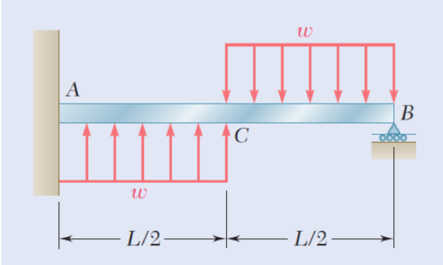
Fig. P9.30
Find the reaction at the roller support and the deflection at point C of the beam.
Answer to Problem 30P
The reaction at the roller support B is
The deflection at point C of the beam is
Explanation of Solution
Consider a section at a distance x from left end A of the section AC.
Show the free-body diagram of the section AC as in Figure 1.
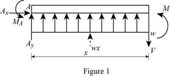
Determine the moment at the section by taking moment about the section.
Write the second order differential equation as follows;
Here, the moment at the corresponding section is
Substitute
Integrate the equation with respect to x;
Integrate the Equation (2) with respect to x.
Show the free-body diagram of the section BC as in Figure 2.
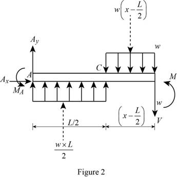
Determine the moment at the section by taking moment about the section.
Substitute
Integrate the equation with respect to x;
Integrate the Equation (4) with respect to x.
Boundary condition 1:
At the point A;
Substitute 0 for x and 0 for y in Equation (3).
Boundary condition 2:
At the point A;
Substitute 0 for x and 0 for
Boundary condition 3:
At the point C;
Equate Equation (2) and (4).
Substitute
Boundary condition 4:
At the point C;
Equate Equation (3) and (5).
Substitute
Boundary condition 5:
At the point B;
Substitute L for x, 0 for y,
Show the free-body diagram of the beam AB as in Figure 3.
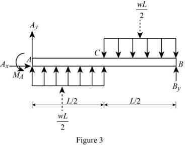
Resolve the vertical component of forces as follows;
Take moment about the point A as follows;
Substitute
Therefore, the reaction at the roller support B is
Substitute
Substitute
At point C;
Substitute
Therefore, the deflection at point C of the beam is
Want to see more full solutions like this?
Chapter 9 Solutions
Mechanics of Materials - With Access


- https://www.chegg.com/homework-help/questions-and-answers/calculate-maximum-deflection-slope-cantilever-steel-beam-length-2-m-cross-section-30-mm-x--q39821709#question-transcriptarrow_forwardDetermine the maximum deflection of a simply supported beam, 6 m long and carrying a uniformly distributed load of 200 N/m applied over its entire length.arrow_forwardKnowing that beam AB is an S200 * 34 rolled shape and that P=60 kN, L= 2 m, and E= 200 GPa, determine (a) the slope at A, (b) the deflection at C.arrow_forward
- A simply-supported beam, 9 m in length, is subjected to a uniform load of 20 kN/m applied at the beam's middle third. Determine the deflection at x = 7.5. Answer: _____/EIarrow_forwardUsing Castigliano’s theorem, determine horizontal and vertical components of deflection at point C. Given: P=1000 N EA= 2*10^6 Narrow_forwardEach of the links AB and CD is made of aluminum and has a cross-sectional area of 0.19 sq.in. Knowing that they support the rigid member BC, determine the downward deflection (in inches) of point E. if x = 12 in, y = 28.8 in, z = 21 in, E = 10817638 psi, and P = 35 kips. Round off the final answer to five decimal places.arrow_forward
- Two rods AB and BC of the same flexural rigidity EI are welded together at B. For the loading shown,determine (a) the deflection of point C, (b) the slope of member BC at point C. (Use energy methods)arrow_forwardThe rod ABC is made of an aluminum for which E = 71.4 GPa. Knowing that P = 7.94 kNand Q = 49.88 kN,determine the deflection (in μm) of point B if y = 0.47 and z = 0.54. Round off the final answer in four decimal places.arrow_forwardFor the beam and loading shown, determine the deflection at point C. Use E=29 *106 psi..arrow_forward
- A 4-ft section of aluminum pipe of cross-sectional area 1.75 in2 rests on a fixed support at A. The 58-in.-diameter steel rod BC hangs from a rigid bar that rests on the top of the pipe at B. Knowing that the smodulus of elasticity is 29 3 106 psi for steel and 10.4 3 106 psi for aluminum, determine the deflection of point C when a 15-kip force is applied at C.arrow_forwardDetermine the maximum deflection of the beam and the slope at ?. Consider ?? constantarrow_forwardDraw the influence lines for the vertical reactions at supports A and E and the reaction moment at support E of the beam shown in Fig. P8.13.arrow_forward
 Elements Of ElectromagneticsMechanical EngineeringISBN:9780190698614Author:Sadiku, Matthew N. O.Publisher:Oxford University Press
 Mechanics of Materials (10th Edition)Mechanical EngineeringISBN:9780134319650Author:Russell C. HibbelerPublisher:PEARSON
 Thermodynamics: An Engineering ApproachMechanical EngineeringISBN:9781259822674Author:Yunus A. Cengel Dr., Michael A. BolesPublisher:McGraw-Hill Education
 Control Systems EngineeringMechanical EngineeringISBN:9781118170519Author:Norman S. NisePublisher:WILEY
 Mechanics of Materials (MindTap Course List)Mechanical EngineeringISBN:9781337093347Author:Barry J. Goodno, James M. GerePublisher:Cengage Learning
 Engineering Mechanics: StaticsMechanical EngineeringISBN:9781118807330Author:James L. Meriam, L. G. Kraige, J. N. BoltonPublisher:WILEY