Mechanics of Materials - With Access
7th Edition
ISBN: 9781259279881
Author: BEER
Publisher: MCG
expand_more
expand_more
format_list_bulleted
Concept explainers
Videos
Textbook Question
Chapter 9.4, Problem 94P
Use the method of superposition to solve the following problems and assume that the flexural rigidity El of each beam is constant.
9.94 A 16-mm-diameter rod has been bent into the shape shown. Determine the deflection of end C after the 200-N force is applied. Use E = 200 GPa and G = 80 GPa.
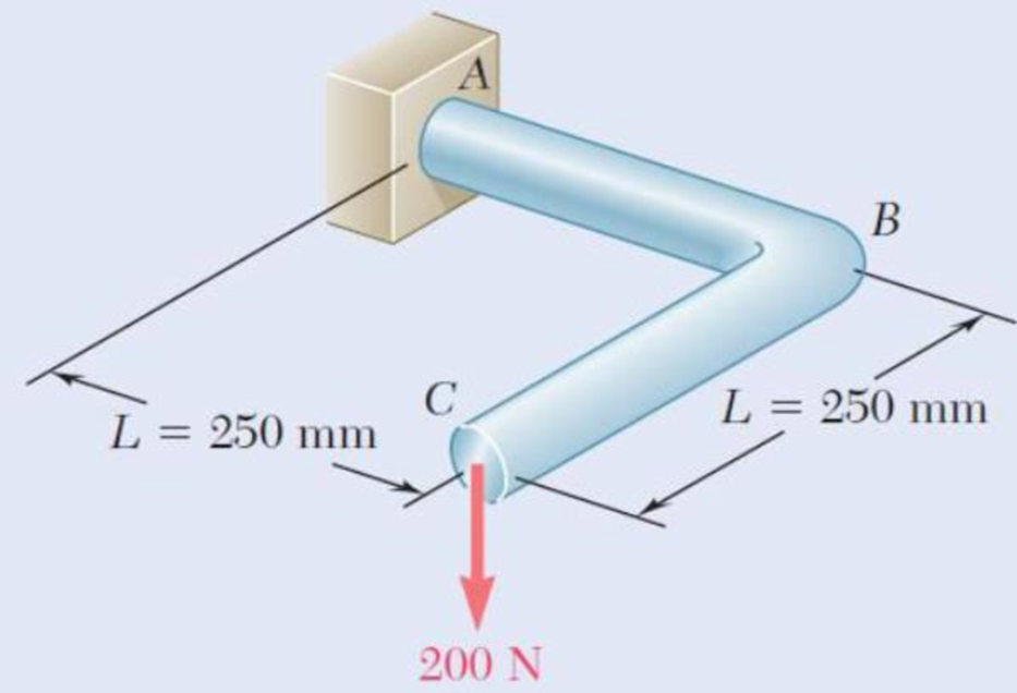
Fig. P9.94
Expert Solution & Answer
Want to see the full answer?
Check out a sample textbook solution
Students have asked these similar questions
A 7/8-in.-diameter rod BC is attached to the lever AB and to the fixed support at C. Lever AB has a uniform cross section 38 in. thick and 1 in. deep. For the loading shown, determine the deflection of point A. Use E=29 *106 psi and G=11.2 *106 psi.
Determine the maximum deflection of a simply supported beam, 6 m long and carrying a uniformly distributed load of 200 N/m applied over its entire length.
A simply-supported beam, 9 m in length, is subjected to a uniform load of 20 kN/m applied at the beam's middle third. Determine the maximum deflection.
Answer: _____/EI
Chapter 9 Solutions
Mechanics of Materials - With Access
Ch. 9.2 - In the following problems assume that the flexural...Ch. 9.2 - In the following problems assume that the flexural...Ch. 9.2 - In the following problems assume that the flexural...Ch. 9.2 - 9.1 through 9.4 For the loading shown, determine...Ch. 9.2 - 9.5 and 9.6 For the cantilever beam and loading...Ch. 9.2 - 9.5 and 9.6 For the cantilever beam and loading...Ch. 9.2 - For the beam and loading shown, determine (a) the...Ch. 9.2 - For the beam and loading shown, determine (a) the...Ch. 9.2 - Knowing that beam .AB is a W10 33 rolled shape...Ch. 9.2 - Knowing that beam AB is an S200 34 roiled shape...
Ch. 9.2 - For the beam and loading shown, (a) express the...Ch. 9.2 - (a) Determine the location and magnitude of the...Ch. 9.2 - For the beam and loading shown, determine the...Ch. 9.2 - Knowing that beam AE is a W360 101 rolled shape...Ch. 9.2 - For the beam and loading shown, knowing that a = 2...Ch. 9.2 - Knowing that beam AE is an S200 27.4 rolled shape...Ch. 9.2 - For the beam and loading shown, determine (a) the...Ch. 9.2 - For the beam and loading shown, determine (a) the...Ch. 9.2 - 9.19 through 9.22 For the beam and loading shown,...Ch. 9.2 - 9.19 through 9.22 For the beam and loading shown,...Ch. 9.2 - 9.19 through 9.22 For the beam and loading shown,...Ch. 9.2 - 9.19 through 9.22 For the beam and loading shown,...Ch. 9.2 - For the beam shown, determine the reaction at the...Ch. 9.2 - For the beam shown, determine the reaction at the...Ch. 9.2 - 9.25 through 9.28 Determine the reaction at the...Ch. 9.2 - 9.25 through 9.28 Determine the reaction at the...Ch. 9.2 - Prob. 27PCh. 9.2 - 9.25 through 9.28 Determine the reaction at the...Ch. 9.2 - 9.29 and 9.30 Determine the reaction at the roller...Ch. 9.2 - 9.29 and 9.30 Determine the reaction at the roller...Ch. 9.2 - 9.37 and 9.32 Determine the reaction at the roller...Ch. 9.2 - 9.31 and 9.32 Determine the reaction at the roller...Ch. 9.2 - Prob. 33PCh. 9.2 - 9.33 and 9.34 determine the reaction at A and draw...Ch. 9.3 - 9.35 and 9.36 For the beam and loading shown,...Ch. 9.3 - 9.35 and 9.36 For the beam and loading shown,...Ch. 9.3 - 9.37 and 9.38 For the beam and loading shown,...Ch. 9.3 - 9.37 and 9.38 For the beam and loading shown,...Ch. 9.3 - 9.39 and 9.40 For the beam and loading shown,...Ch. 9.3 - 9.39 and 9.40 For the beam and loading shown,...Ch. 9.3 - 9.41 and 9.42 For the beam and loading shown,...Ch. 9.3 - 9.41 and 9.42 For the beam and loading shown (a)...Ch. 9.3 - For the beam and loading shown, determine (a) the...Ch. 9.3 - For the beam and loading shown, determine (a) the...Ch. 9.3 - For the timber beam and loading shown, determine...Ch. 9.3 - For the beam and loading shown, determine (a) the...Ch. 9.3 - For the beam and loading shown, determine (a) the...Ch. 9.3 - For the beam and loading shown, determine (a) the...Ch. 9.3 - 9.49 and 9.50 For the beam and loading shown,...Ch. 9.3 - 9.49 and 9.50 For the beam and loading shown,...Ch. 9.3 - 9.51 and 9.52 For the beam and loading shown,...Ch. 9.3 - 9.49 and 9.50 For the beam and loading shown,...Ch. 9.3 - For the beam and loading shown, determine (a) the...Ch. 9.3 - For the beam shown, and knowing that P = 40 kN,...Ch. 9.3 - 9.55 and 9.56 For the beam and loading shown, (a)...Ch. 9.3 - 9.55 and 9.56 For the beam and loading shown, (a)...Ch. 9.3 - For the beam and loading shown, determine (a) the...Ch. 9.3 - For the beam and loading shown, determine (a) the...Ch. 9.3 - Prob. 59PCh. 9.3 - 9.59 through 9.62 For the beam and loading...Ch. 9.3 - Prob. 61PCh. 9.3 - 9.59 through 9.62 For the beam and loading...Ch. 9.3 - The rigid bars BF and DH are welded to the...Ch. 9.3 - The rigid bar DEF is welded at point D to the...Ch. 9.4 - Use the method of superposition to solve the...Ch. 9.4 - Use the method of superposition to solve the...Ch. 9.4 - Use the method of superposition to solve the...Ch. 9.4 - Use the method of superposition to solve the...Ch. 9.4 - Use the method of superposition to solve the...Ch. 9.4 - Use the method of superposition to solve the...Ch. 9.4 - Use the method of superposition to solve the...Ch. 9.4 - Use the method of superposition to solve the...Ch. 9.4 - Use the method of superposition to solve the...Ch. 9.4 - Use the method of superposition to solve the...Ch. 9.4 - Use the method of superposition to solve the...Ch. 9.4 - Use the method of superposition to solve the...Ch. 9.4 - Use the method of superposition to solve the...Ch. 9.4 - Use the method of superposition to solve the...Ch. 9.4 - Use the method of superposition to solve the...Ch. 9.4 - Use the method of superposition to solve the...Ch. 9.4 - Use the method of superposition to solve the...Ch. 9.4 - Use the method of superposition to solve the...Ch. 9.4 - Use the method of superposition to solve the...Ch. 9.4 - Prob. 84PCh. 9.4 - Use the method of superposition to solve the...Ch. 9.4 - Use the method of superposition to solve the...Ch. 9.4 - Use the method of superposition to solve the...Ch. 9.4 - Use the method of superposition to solve the...Ch. 9.4 - Use the method of superposition to solve the...Ch. 9.4 - Use the method of superposition to solve the...Ch. 9.4 - Use the method of superposition to solve the...Ch. 9.4 - Use the method of superposition to solve the...Ch. 9.4 - Use the method of superposition to solve the...Ch. 9.4 - Use the method of superposition to solve the...Ch. 9.5 - 9.95 through 9.98 For the uniform cantilever beam...Ch. 9.5 - Prob. 96PCh. 9.5 - 9.95 through 9.98 For the uniform cantilever beam...Ch. 9.5 - 9.95 through 9.98 For the uniform cantilever beam...Ch. 9.5 - 9.99 and 9.100 For the uniform cantilever beam and...Ch. 9.5 - 9.99 and 9.100 For the uniform cantilever beam and...Ch. 9.5 - For the cantilever beam and loading shown,...Ch. 9.5 - Prob. 102PCh. 9.5 - Prob. 103PCh. 9.5 - Prob. 104PCh. 9.5 - Prob. 105PCh. 9.5 - For the cantilever beam and loading shown,...Ch. 9.5 - Two cover plates are welded to the rolled-steel...Ch. 9.5 - Two cover plates are welded to the rolled-steel...Ch. 9.5 - 9.109 through 9.114 For the prismatic beam and...Ch. 9.5 - Prob. 110PCh. 9.5 - Prob. 111PCh. 9.5 - Prob. 112PCh. 9.5 - Prob. 113PCh. 9.5 - Prob. 114PCh. 9.5 - Prob. 115PCh. 9.5 - 9.115 and 9.116 For the beam and loading shown,...Ch. 9.5 - Prob. 117PCh. 9.5 - 9.118 and 9.119 For the beam and loading shown,...Ch. 9.5 - Prob. 119PCh. 9.5 - Prob. 120PCh. 9.5 - Prob. 121PCh. 9.5 - Prob. 122PCh. 9.5 - Prob. 123PCh. 9.5 - Prob. 124PCh. 9.6 - 9.125 through 9.128 For the prismatic beam and...Ch. 9.6 - Prob. 126PCh. 9.6 - Prob. 127PCh. 9.6 - Prob. 128PCh. 9.6 - 9.129 and 9.130 For the beam and loading shown,...Ch. 9.6 - Prob. 130PCh. 9.6 - For the timber beam and loading shown, determine...Ch. 9.6 - Prob. 132PCh. 9.6 - For the beam and loading shown, determine (a) the...Ch. 9.6 - Prob. 134PCh. 9.6 - Prob. 135PCh. 9.6 - Knowing that the beam AD is made of a solid steel...Ch. 9.6 - Prob. 137PCh. 9.6 - For the beam and loading shown, determine (a) the...Ch. 9.6 - Prob. 139PCh. 9.6 - For the beam and loading shown, determine the...Ch. 9.6 - Prob. 141PCh. 9.6 - Prob. 142PCh. 9.6 - Prob. 143PCh. 9.6 - Prob. 144PCh. 9.6 - Prob. 145PCh. 9.6 - For the beam and loading shown, determine (a) the...Ch. 9.6 - Prob. 147PCh. 9.6 - Prob. 148PCh. 9.6 - Prob. 149PCh. 9.6 - Prob. 150PCh. 9.6 - 9.151 and 9.152 For the beam and loading shown,...Ch. 9.6 - Prob. 152PCh. 9.6 - Prob. 153PCh. 9.6 - Prob. 154PCh. 9.6 - Prob. 155PCh. 9.6 - Fig. P9.155 and P9.156 9.156 For the beam and...Ch. 9 - For the loading shown, determine (a) the equation...Ch. 9 - Prob. 158RPCh. 9 - For the beam and loading shown, determine (a) the...Ch. 9 - Determine the reaction at A and draw the bending...Ch. 9 - For the beam and loading shown, determine (a) the...Ch. 9 - For the beam and loading shown, determine (a) the...Ch. 9 - Beam CE rests on beam AB as shown. Knowing that a...Ch. 9 - The cantilever beam BC is attached to the steel...Ch. 9 - For the cantilever beam and loading shown,...Ch. 9 - Knowing that P = 4 kips, determine (a) the slope...Ch. 9 - For the beam and loading shown, determine (a) the...Ch. 9 - Determine the reaction at the roller support and...
Knowledge Booster


Learn more about
Need a deep-dive on the concept behind this application? Look no further. Learn more about this topic, mechanical-engineering and related others by exploring similar questions and additional content below.Similar questions
- A central beam BD is joined by hinges to two cantilever beams AB and DE. All beams have the cross section shown. For the loading shown, determine the largest w so that the deflection at C does not exceed 3 mm. Use E=200 GPa.arrow_forwardDetermine the shape of a fully stressed, simply supported beam that supportsa concentrated force at its center, Fig. 11–11a. The beam has a rectangularcross section of constant width b, and the allowable stress is sallow.arrow_forwardEach of the links AB and CD is made of aluminum and has a cross-sectional area of 0.2 sq.in. Knowing that they support the rigid member BC, determine the downward deflection (in inches) of point C. if x = 13.7 in, y = 28.1 in, z = 20 in, E = 10754407 psi, and P = 26 kips.arrow_forward
- https://www.chegg.com/homework-help/questions-and-answers/calculate-maximum-deflection-slope-cantilever-steel-beam-length-2-m-cross-section-30-mm-x--q39821709#question-transcriptarrow_forwardThe rod ABC is made of an aluminum for which E = 71.4 GPa. Knowing that P = 7.94 kNand Q = 49.88 kN,determine the deflection (in μm) of point B if y = 0.47 and z = 0.54. Round off the final answer in four decimal places.arrow_forwardA cable AB of span L and a simple beam A'B' of the same span are subjected to identical vertical loadings as shown. Show that the magnitude of the bending moment at a point C' in the beam is equal to the product T0h, where T0 is the magnitude of the horizontal component of the tension force in the cable and h is the vertical distance between point C and the chord joining the points of support A and B.arrow_forward
- For the beam and loading shown, determine the deflection at point C. Use E=29 *106 psi..arrow_forwardA 4-ft section of aluminum pipe of cross-sectional area 1.75 in2 rests on a fixed support at A. The 58-in.-diameter steel rod BC hangs from a rigid bar that rests on the top of the pipe at B. Knowing that the smodulus of elasticity is 29 3 106 psi for steel and 10.4 3 106 psi for aluminum, determine the deflection of point C when a 15-kip force is applied at C.arrow_forwardEach of the links AB and CD is made of aluminum and has a cross-sectional area of 0.19 sq.in. Knowing that they support the rigid member BC, determine the downward deflection (in inches) of point E. if x = 12 in, y = 28.8 in, z = 21 in, E = 10817638 psi, and P = 35 kips. Round off the final answer to five decimal places.arrow_forward
- Q2: By moment area method determine the slope and deflection at point B for the following cantilever beam. w W/marrow_forwardconsider the cantilevered W14 x 30 beam shown E = 29(103) ksi, I = 291 in4 determine the maximum slope of the beam, measured counterclockwise from the positive x axis. determine the maximum deflection of the beam. determine the expression for the elastic curve using the coordinate x for 0 < x < 9 ft, where x is in feet.arrow_forwardThe 70-mm-diameter steel rod ABC, and a brass rod CD of the same diameter, are joined at point C to form the 7.5-m long rod “ABCD”. E’s for the materials in the rod are shown in the picture below. For the loading shown, and neglecting the weight of the rod, determine: a) the deflection of point B b) the deflection of point C c) the deflection of point D d) the longitudinal stress in the middle of section AB e) the longitudinal stress in the middle of section BC f) the longitudinal stress in the middle of section CD a) all elemental stiffness matrices, b) the force matrix, and the c) assembly stiffness matrixarrow_forward
arrow_back_ios
SEE MORE QUESTIONS
arrow_forward_ios
Recommended textbooks for you
 Elements Of ElectromagneticsMechanical EngineeringISBN:9780190698614Author:Sadiku, Matthew N. O.Publisher:Oxford University Press
 Mechanics of Materials (10th Edition)Mechanical EngineeringISBN:9780134319650Author:Russell C. HibbelerPublisher:PEARSON
 Thermodynamics: An Engineering ApproachMechanical EngineeringISBN:9781259822674Author:Yunus A. Cengel Dr., Michael A. BolesPublisher:McGraw-Hill Education
 Control Systems EngineeringMechanical EngineeringISBN:9781118170519Author:Norman S. NisePublisher:WILEY
 Mechanics of Materials (MindTap Course List)Mechanical EngineeringISBN:9781337093347Author:Barry J. Goodno, James M. GerePublisher:Cengage Learning
 Engineering Mechanics: StaticsMechanical EngineeringISBN:9781118807330Author:James L. Meriam, L. G. Kraige, J. N. BoltonPublisher:WILEY
Elements Of Electromagnetics
Mechanical Engineering
ISBN:9780190698614
Author:Sadiku, Matthew N. O.
Publisher:Oxford University Press
Mechanics of Materials (10th Edition)
Mechanical Engineering
ISBN:9780134319650
Author:Russell C. Hibbeler
Publisher:PEARSON
Thermodynamics: An Engineering Approach
Mechanical Engineering
ISBN:9781259822674
Author:Yunus A. Cengel Dr., Michael A. Boles
Publisher:McGraw-Hill Education
Control Systems Engineering
Mechanical Engineering
ISBN:9781118170519
Author:Norman S. Nise
Publisher:WILEY
Mechanics of Materials (MindTap Course List)
Mechanical Engineering
ISBN:9781337093347
Author:Barry J. Goodno, James M. Gere
Publisher:Cengage Learning
Engineering Mechanics: Statics
Mechanical Engineering
ISBN:9781118807330
Author:James L. Meriam, L. G. Kraige, J. N. Bolton
Publisher:WILEY
Solids: Lesson 53 - Slope and Deflection of Beams Intro; Author: Jeff Hanson;https://www.youtube.com/watch?v=I7lTq68JRmY;License: Standard YouTube License, CC-BY