
Mechanics of Materials
11th Edition
ISBN: 9780137605514
Author: Russell C. Hibbeler
Publisher: Pearson Education (US)
expand_more
expand_more
format_list_bulleted
Concept explainers
Videos
Textbook Question
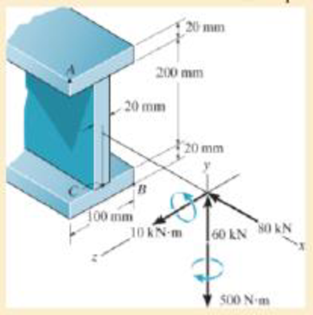
Chapter 9.3, Problem 25P
The internal loadings at a section of the beam are shown. Determine the in-plane principal stresses at point A. Also compute the maximum in-plane shear stress at this point.
Expert Solution & Answer
Want to see the full answer?
Check out a sample textbook solution
Students have asked these similar questions
Use Mohr’s circle to determine the principal stresses at the point. Also, find the corresponding orientation of the element with respect to the element shown.
The main stress, the maximum shear stress, and the dead angle are obtained when the stress is given as shown in the picture below.Draw Mohr's circle.
1. Determine the stresses for a square stress element on top of CD at point D. The stress element is aligned with CD. Then determine the maximum normal and maximum shear stress at the same point for the stress element. CD is 36 mm in diameter and BC is 24 mm diameter. Both are solid.
2. For the beam shown determine the stress for a stress element on top, similar to point H, but at the wall A instead (centered on top at the wall). Then determine the maximum normal and shear stress for that stress element.
Chapter 9 Solutions
Mechanics of Materials
Ch. 9.3 - Determine the normal stress and shear stress...Ch. 9.3 - Determine the equivalent state of stress on an...Ch. 9.3 - Also, find the corresponding orientation of the...Ch. 9.3 - Determine the equivalent state of stress on an...Ch. 9.3 - Determine the maximum principal stress at point B.Ch. 9.3 - Determine the principal stress at point C.Ch. 9.3 - Determine the stress components acting on the...Ch. 9.3 - Solve Prob.99 using the stress transformation...Ch. 9.3 - Determine the stress components acting on the...Ch. 9.3 - Determine the equivalent state of stress on an...
Ch. 9.3 - The stress along two planes at a point is...Ch. 9.3 - The state of stress at a point in a member is...Ch. 9.3 - The wood beam is subjected to a load of 12 kN. If...Ch. 9.3 - The internal loadings at a section of the beam are...Ch. 9.3 - Solve Prob.925 for point B. 925. The internal...Ch. 9.3 - Solve Prob.925 for point C. 925. The internal...Ch. 9.3 - It is subjected to a torque of 12 kip in. and a...Ch. 9.3 - A paper tube is formed by rolling a cardboard...Ch. 9.3 - Solve Prob.931 for the normal stress acting...Ch. 9.3 - Determine the principal stresses in the...Ch. 9.3 - The shaft has a diameter d and is subjected to the...Ch. 9.4 - Use Mohrs circle to determine the normal stress...Ch. 9.4 - Also, find the corresponding orientation of the...Ch. 9.4 - Draw Mohrs circle and determine the principal...Ch. 9.4 - Determine the principal stresses at a point on the...Ch. 9.4 - Determine the principal stresses at point A on the...Ch. 9.4 - Point A is just below the flange.Ch. 9.4 - Mohrs circle for the state of stress is shown in...Ch. 9.4 - Determine (a) the principal stresses and (b) the...Ch. 9.4 - Determine the equivalent state of stress if an...Ch. 9.4 - Draw Mohrs circle that describes each of the...Ch. 9.4 - Draw Mohrs circle trial describes each of the...Ch. 9.4 - Determine (a) the principal stresses and (b) the...Ch. 9.4 - Determine (a) the principal stresses and (b) the...Ch. 9.4 - Draw Mohrs circle that describes each of the...Ch. 9.4 - The grains of wood in the board make an angle of...Ch. 9.4 - A spherical pressure vessel has an inner radius of...Ch. 9.4 - The cylindrical pressure vessel has an inner...Ch. 9.4 - If the box wrench is subjected to the 50 lb force,...Ch. 9.4 - If the box wrench is subjected to the 50-lb force,...Ch. 9.5 - Draw the three Mohrs circles that describe each of...Ch. 9.5 - Draw the three Mohrs circles that describe the...Ch. 9.5 - Determine the principal stresses and the absolute...Ch. 9.5 - The solid shaft is subjected to a torque, bending...Ch. 9.5 - The frame is subjected to a horizontal force and...Ch. 9 - Prob. 1RPCh. 9 - The steel pipe has an inner diameter of 2.75 in....Ch. 9 - Determine the equivalent state of stress If an...Ch. 9 - The crane is used to support the 350-lb load....Ch. 9 - Determine the equivalent state of stress on an...Ch. 9 - The propeller shaft of the tugboat is subjected to...Ch. 9 - Determine the principal stresses in the box beam...Ch. 9 - Determine (a) the principal stresses and (b) the...Ch. 9 - Determine the stress components acting on the...
Knowledge Booster


Learn more about
Need a deep-dive on the concept behind this application? Look no further. Learn more about this topic, mechanical-engineering and related others by exploring similar questions and additional content below.Similar questions
- The box beam is subjected to the 26-kN force that is applied at the center of its width, 75 mm from each side. Determine the principal stresses at point A and show the results in an element located at this point. Use the shear formula to calculate the shear stress.arrow_forwardThe forces applied to pulleys are given as shown below. Accordingly, show the stress state at point A on a 2-dimensional stress element and find the Von-Misses equivalent stress.arrow_forwardThe internal loadings at a cross section through the 6-in.-diameter drive shaft of a turbine consist of an axial force of 2500 lb, a bending moment of 800 lb # ft, and a torsional moment of 1500 lb # ft. Determine the principal stresses at point B. Also calculate the maximum in-plane shear stress at this point.arrow_forward
- 1. The pictured link acts as a part of the elevator control for a small airplane. If the attached aluminum tube has an inner diameter of 25 mm and a wall thickness of 5 mm, determine the shear stress in the outer and inner surfaces of the tube when a cable force of 600 N is applied to the cables. Also, sketch the shear-stress distribution over the cross-section.arrow_forwardThe bent pipe has a 1.5-in. outer diameter and a 0.2-in. wall thickness. Calculate the largest shear stress that occurs in (a) segment BC; and (b) segment AB. Neglect the stress due to the transverse shear force.arrow_forwardThe internal loadings at a cross section through the 6-in.-diameter drive shaft of a turbine consist of an axial force of 2500 lb, a bending moment of 800 lb # ft, and a torsional moment of 1500 lb # ft. Determine the principal stresses at point A. Also calculate the maximum in-plane shear stress at this point.arrow_forward
- if the maximum and minimum principal stresses at a point are (27 Mpa) and (5 Mpa) respectively. The maximum shear stress at this point isarrow_forwardThe wide-flange beam is subjected to the P = 54 kN force. Determine the principal stresses in the beam at point A located on the web at the bottom of the upper flange. Although it is not very accurate, use the shear formula to calculate the shear stress. (Figure 1)arrow_forwardUse Mohrs circle to find the principle stresses and determine the normal and shear stresses acting on a plane 45 degrees counter clockwise from the Y-plane. Sketch showing the exterior stresses.arrow_forward
- State of stress at the wall and the roof of the following circular opening bafore the excavation is (a] = |0 4. Find the induced stress components at point a. R W with respect to the given x-y coordinate systerm, and expresst them in the matrix form. b. Find the total stresses at point W, and give them in matrix form. c. Repeat (a) and (b) for the roof. d. Find the stresses oy, Ciy, and tyy at point A which is located at a radial distance twice the radius of the tunnel.arrow_forwardFind normal and shearing stresses at point A .And construct the state of stress at Aarrow_forwardUse Mohr’s circle to determine the normal stress and shear stress acting on the inclined plane AB.arrow_forward
arrow_back_ios
SEE MORE QUESTIONS
arrow_forward_ios
Recommended textbooks for you
 Elements Of ElectromagneticsMechanical EngineeringISBN:9780190698614Author:Sadiku, Matthew N. O.Publisher:Oxford University Press
 Mechanics of Materials (10th Edition)Mechanical EngineeringISBN:9780134319650Author:Russell C. HibbelerPublisher:PEARSON
 Thermodynamics: An Engineering ApproachMechanical EngineeringISBN:9781259822674Author:Yunus A. Cengel Dr., Michael A. BolesPublisher:McGraw-Hill Education
 Control Systems EngineeringMechanical EngineeringISBN:9781118170519Author:Norman S. NisePublisher:WILEY
 Mechanics of Materials (MindTap Course List)Mechanical EngineeringISBN:9781337093347Author:Barry J. Goodno, James M. GerePublisher:Cengage Learning
 Engineering Mechanics: StaticsMechanical EngineeringISBN:9781118807330Author:James L. Meriam, L. G. Kraige, J. N. BoltonPublisher:WILEY
Elements Of Electromagnetics
Mechanical Engineering
ISBN:9780190698614
Author:Sadiku, Matthew N. O.
Publisher:Oxford University Press
Mechanics of Materials (10th Edition)
Mechanical Engineering
ISBN:9780134319650
Author:Russell C. Hibbeler
Publisher:PEARSON
Thermodynamics: An Engineering Approach
Mechanical Engineering
ISBN:9781259822674
Author:Yunus A. Cengel Dr., Michael A. Boles
Publisher:McGraw-Hill Education
Control Systems Engineering
Mechanical Engineering
ISBN:9781118170519
Author:Norman S. Nise
Publisher:WILEY
Mechanics of Materials (MindTap Course List)
Mechanical Engineering
ISBN:9781337093347
Author:Barry J. Goodno, James M. Gere
Publisher:Cengage Learning
Engineering Mechanics: Statics
Mechanical Engineering
ISBN:9781118807330
Author:James L. Meriam, L. G. Kraige, J. N. Bolton
Publisher:WILEY
Understanding Stress Transformation and Mohr's Circle; Author: The Efficient Engineer;https://www.youtube.com/watch?v=_DH3546mSCM;License: Standard youtube license