
Concept explainers
Videos
Repeat Problem 1.47 if the reverse−saturation current for each diode isy
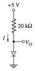
a.
The voltage across diode.
Answer to Problem 1.48P
The diode voltage,
Explanation of Solution
Given information:
The circuit diagram is given as:
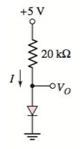
The reverse saturation current for each diode is
Calculation:
The expression for the diode current is given as:
From the given circuit, evaluating the diode current:
From the circuit, the output voltage is same as the diode voltage.
Solving equation 1 and 2 by using the hit and trial method:
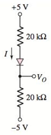
b.
The voltage across diode.
Answer to Problem 1.48P
The diode voltage,
Explanation of Solution
Given information:
The circuit diagram is given as:
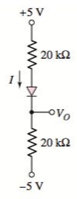
The reverse saturation current for each diode is
Calculation:
The expression for the diode current is given as:
From the given circuit, evaluating the diode current:
Applying the Kirchhoff’s voltage law to the circuit from top to bottom:
Assuming the voltage across diode vD, then applying the Kirchhoff’s voltage law from top to the output voltage:
From the circuit, the diode current is same as the current flowing in the circuit:
Solving equation 1, 2 and 3 by using the hit and trial method:
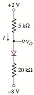
c.
The voltage across diode.
Answer to Problem 1.48P
The diode voltage,
Explanation of Solution
Given information:
The circuit diagram is given as:
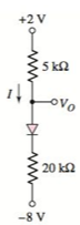
The reverse saturation current for each diode is
Calculation:
The expression for the diode current is given as:
From the given circuit, evaluating the diode current:
Applying the Kirchhoff’s voltage law to the circuit from top to bottom:
Then applying the Kirchhoff’s voltage law from top to the output voltage:
From the circuit, the diode current is same as the current flowing in the circuit:
Solving equation 1, 2 and 3 by using the hit and trial method:
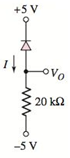
d.
The voltage across diode.
Answer to Problem 1.48P
The diode voltage,
Explanation of Solution
Given information:
The circuit diagram is given as:
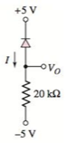
The reverse saturation current for each diode is
Calculation:
Referring the given circuit, here the diode current is flowing in the reverse direction.
Hence, the reverse saturation current will be the diode current in this case.
Since the value of the reverse saturation current is given in the question.
Therefore,
Now evaluating the diode voltage:
Since, due to reverse direction of the current, no current will flow through the resistor. Hence the drop across the resistor will be zero.
Therefore, the value of the diode voltage will be same as the output voltage:
Want to see more full solutions like this?
Chapter 1 Solutions
Microelectronics: Circuit Analysis and Design


- What is CEMF?arrow_forwardb. Calculate the following about the circuit in Figure 2.1 (If silicon diodes are employed in therectification);i. the peak value of the output voltage considering the drop across each diode, Vpk.ii. the average voltage, Vdc.iii. The current through the load resistor, IL.iv. The current diode, Id.v. The frequency of the output signal, Fout.vi. Calculate the efficiency of the full wave rectifier expressed in percentage.vii. Sketch a graph of the input and output voltage against time.arrow_forward(I) Determine the average ac resistance for the diode of the Figure below for the region between 0.6 V and 0.9 V. (II) Then determine the ac resistance for the diode of the Figure below at 0.75 V and compare it to the average ac resistance obtained in (I).arrow_forward
- Calculate the new threshold voltage of a germanium diode when it operates at 100-degrees centigrade. Considering the room temperature is 25-degrees centigrade.arrow_forwardaccepting that D1 and D2 diodes have the same properties in the circuit given in the figurea) output voltage, b) current flowing through the resistor,c) current flowing from diodes calculate.arrow_forwardQ1 (a) For the given circuit in Figure Q1.1, (i) Describe the diode representation as a switch (ii) Identify the condition of the diode and its equivalent circuit. (iii) Calculate ID, VR1, VR2 and Vo with the diode represent as a switch. (iv) Perform the same calculation as (ii) for GaAs diode.arrow_forward
- 2-2VOLTAGE-CURRENT CHARACTERISTICOF A DIODE 1.Explain how to generate the forward-bias portion of the characteristic curve. 2.What would cause the barrier potential of a silicon diode to decrease from 0.7 V to 0.6 V?arrow_forwardDetermine zener diode voltage value as well as the ripple percentage pf teh circuit below with 240Vpp. Please answer it with clear and complete solution. Thank you. This subject is Electronics 1.arrow_forwardDraw the V-I characteristic curve of a Ge based Zener diode with Zener breakdown voltage (?z=5 ?). Indicate three different regions of the curve. Subject: Electronic devicesarrow_forward
- a) Determine voltages across resistance using 1st approximation. b) Determine currents across diodes using 2nd approximationarrow_forwardDetermine zener diode voltage value as well as the ripple percentage of the circuit below with 240Vpp. Please answer it clear with complete solutions. Thank you. This subject is Electronics 1.arrow_forwardDraw sketches to illustrate the behaviour of the following: i. Reverse Biased Zener Diode ii. Ideal Diode iii. Forward Biased Practical Diode iv. Equivalent circuit of a simple diode circuit v. Practical Diode at Average AC Resistance Levelarrow_forward

 Electricity for Refrigeration, Heating, and Air C...Mechanical EngineeringISBN:9781337399128Author:Russell E. SmithPublisher:Cengage Learning
 Delmar's Standard Textbook Of ElectricityElectrical EngineeringISBN:9781337900348Author:Stephen L. HermanPublisher:Cengage Learning