
Videos
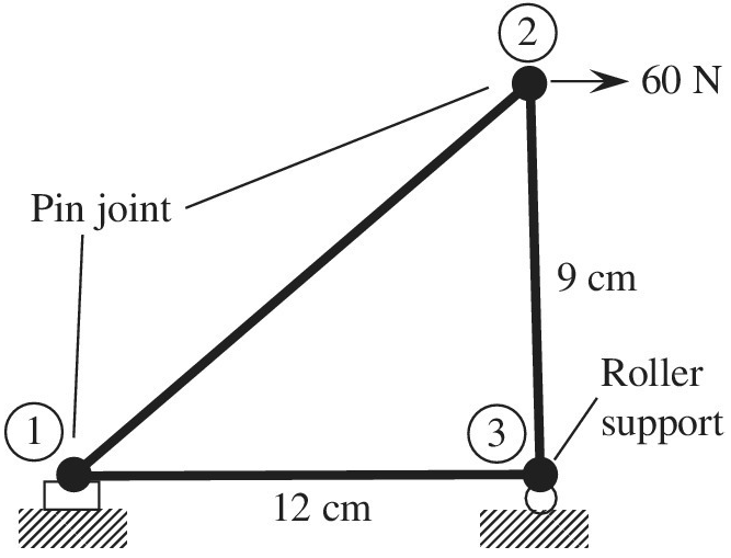
For a two-dimensional truss structure as shown in the figure, determine displacements of the nodes and normal stresses developed in the members using the direct stiffness method. Use
Want to see the full answer?
Check out a sample textbook solution
Chapter 1 Solutions
Introduction To Finite Element Analysis And Design
Additional Engineering Textbook Solutions
Engineering Mechanics: Statics & Dynamics (14th Edition)
Automotive Technology: Principles, Diagnosis, And Service (6th Edition) (halderman Automotive Series)
Fundamentals of Heat and Mass Transfer
Thinking Like an Engineer: An Active Learning Approach (3rd Edition)
Manufacturing Engineering & Technology
Engineering Mechanics: Dynamics (14th Edition)


- The flat bars shown in parts a and b of the figure are subjected to tensile forces P = 2.5 kN. Each bar has thickness t = 5.0 mm. (a) For the bar with a circular hole, determine the maximum stresses for hole diameters d = 12 mm and d = 20 mm il" the width h = 60 mm. (b) For the stepped bar with shoulder fillets, determine the maximum stresses Tor fillet radii R = 6 mm and R = 10 mm if the bar widths are h = 60 mm and c = 40 mm.arrow_forwardA cylindrical pressure vessel having a radius r = 14 in. and wall thickness t = 0,5 in, is subjected to internal pressure p = 375 psi, In addition, a torque T = 90 kip-ft acts at each end of the cylinder (see figure), (a) Determine the maximum tensile stress ctniXand the maximum in-plane shear stress Tmjv in the wall of the cylinder. (b) If the allowable in-plane shear stress is 4.5 ksi, what is the maximum allowable torque T\ (c) If 7 = 150 kip-ft and allowable in-plane shear and allowable normal stresses are 4.5 ksi and 11.5 ksi, respectively, what is the minimum required wall thicknessarrow_forwardA solid circular bar having diameter d is to be replaced by a rectangular tube having cross-sectional dimensions d × 2d to the median line of the cross section (see figure). Determine the required thickness tminof the tube so that the maximum shear stress in the tube will not exceed the maximum shear stress in the solid bar.arrow_forward
- A traffic light and signal pole is subjected to the weight of each traffic signal We = 45 lb and the weight of the road lamp WL= 55 lb. The pole is fixed at the base. Find the principal normal stresses and the maximum shear stress on element B located 19 ft above the base (see figure). Assume that the weight of the pole and lateral arms is included in the signal and lamp weightsarrow_forward7.5-11 in. cube of concrete (E = 4.5 X 10⁶ psi. v = 0.2) is compressed in biaxial stress by means of a framework that is loaded as shown in the figure. Assuming that each load F equals 25 kips. determine the change iv in the volume of the cube and the strain energy U stored in the cube.arrow_forward• - 3 A rectangular plate in biaxial stress (see figure) is subjected to normal stresses u = 67 MPa (tension) and s = -23 MPa (compression). The plate has dimensions 400 X 550 X 20 mm and is made of steel with E = 200 GPa and v = 0.30. (a) Determine the maximum in-plane shear strain ?max in the plate. (b) Determine the change ?t in the thickness of the plate. (c) Determine the change ?t in the volume of the plate.arrow_forward
- A prismatic bar with a length L = 3 ft and cross-sectional area A = 8 in2 is compressed by an axial centroidal load P = 10 kips. Determine the complete state of stress acting on an inclined section pq that is cut through the bar at an angle W = 35", and show the stresses on a properly oriented stress element.arrow_forwardThe normal strain in the 45n direction on the surface of a circular tube (sec figure) is 880 × 10 when the torque T = 750 lb-in. The tube is made of copper alloy with G = 6.2 × 10⁶ psi and y = 0.35. If the outside diameter d2of the tube is 0.8 in., what is the inside diameter dt? If the allowable normal stress in the tube is 14 ksi, what is the maximum permissible inside diameter d?arrow_forward-11 A solid steel bar (G = 11.8 X 10⁶ psi ) of diameter d = 2,0 in. is subjected to torques T = 8.0 kip-in. acting in the directions shown in the figure. Determine the maximum shear, tensile, and compressive stresses in the bar and show these stresses on sketches of properly oriented stress elements. Determine the corresponding maximum strains (shear, tensile, and compressive) in the bar and show these strains on sketches of the deformed elements.arrow_forward
- The flat bars shown in parts a and b of the figure are subjected to tensile forces P = 3.0 kips. Each bar a has thickness t = 0.25 in. (a) For the bar with a circular hole, determine the maximum stresses for hole diameters d = 1 in. and d = 2 in. if the width b = 6.0 in. (b) For the stepped bar with shoulder fillets, determine the maximum stresses for fillet radii R = 0.25 in. and R = 0.5 in. if the bar widths are b = 4.0 in. and c = 2.5 in.arrow_forwardA thin-walled circular tube and a solid circular bar of the same material (see figure) are subjected to torsion. The tube and bar have the same cross-sectional area and the same length. What is the ratio of the strain energy U1in the tube to the strain energy U2in the solid bar if the maximum shear stresses are the same in both cases? (For the tube, use the approximate theory for thin-walled bars.)arrow_forwardAn aluminum pole for a street light weighs 4600 N and supports an arm that weighs 660 N (see figure). The center of gravity of the arm is 1.2 m from the axis of the pole, A wind force of 300 N also acts in the (y) direction at 9 m above the base. The outside diameter of the pole (at its base) is 225 mm, and its thickness is 18 mm. Determine the maximum tensile and compressive stresses o, and e1., respectively, in the pole (at its base) due to the weights and the wind force.arrow_forward
 Mechanics of Materials (MindTap Course List)Mechanical EngineeringISBN:9781337093347Author:Barry J. Goodno, James M. GerePublisher:Cengage Learning