
Videos
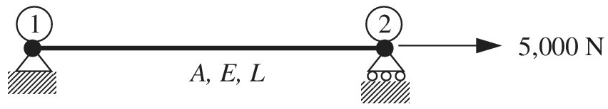
The uniaxial bar shown below can be modeled as a one-dimensional bar. The bar has the following properties:
a. Calculate the global matrix equation after applying boundary conditions.
b. Solve for the displacement
c. What is the element force P in the bar?
Want to see the full answer?
Check out a sample textbook solution
Chapter 1 Solutions
Introduction To Finite Element Analysis And Design
Additional Engineering Textbook Solutions
Introduction to Heat Transfer
INTERNATIONAL EDITION---Engineering Mechanics: Statics, 14th edition (SI unit)
Automotive Technology: Principles, Diagnosis, And Service (6th Edition) (halderman Automotive Series)
Thinking Like an Engineer: An Active Learning Approach (3rd Edition)
Manufacturing Engineering & Technology
DeGarmo's Materials and Processes in Manufacturing


- A W 8 × 28 beam of a length 10 ft is held between immoveable supports. The beam has a modulus of elasticity E = 29,000 ksi and coefficient of thermal expansion a = 6.5 ×10⁻⁶ /?. If the temperature of the beam is raised uniformly by an amount AT = 20°F, calculate the thermal stress aTin the beam.arrow_forwardThe rails of a railroad track are welded together at their ends (to form continuous rails and thus eliminate the clacking sound of the wheels) when the temperature is 60°F. What compressive stress ?? =6.5×10⁻⁶ /? is produced in the rails when they are heated by the sun to 120"F if the coefficient of thermal expansion a = the modulus of elasticity E = 30 × 106 psi?arrow_forwardAn aluminum bar has length L = 6 ft and diameter d = 1.375 in. The stress-strain curse for the aluminum is shown in Fig. 1.34. The initial straight, line part of the curve has a slope (modulus of elasticity) of 10.6 × 10⁶ psi. The bar is loaded by tensile forces P = 44.6 k and then unloaded. (a) That is the permanent set of the bar? (b) If the bar is reloaded. what is the proportional limit? hint: Use the concepts illustrated in Figs. l.39b and 1.40.arrow_forward
- (a) Solve part (a) of the preceding problem if the pressure is 8.5 psi, the diameter is 10 in., the wall thickness is 0,05 in., the modulus of elasticity is 200 psi, and Poisson's ratio is 0.48. (b) If the strain must be limited to 1.01, find the maximum acceptable inflation pressurearrow_forwardAn elastic rubber sphere of radius 20mm is pressed upon a rigid sphere of radius 50mm. The Young’s modulus of rubber is 0.1GPa and the Poisson’s ratio is 0.45. If the maximum allowable pressure below the indenter is 10MPa, determine the maximum contact force that we can apply and the corresponding contact radius.arrow_forwardA steel bar of 5 mm is heated from 15° C to 40° C and it is free to expand. The bar Will induce A. no stress B. shear stress C. tensile stress D. compressive stressarrow_forward
- A circular rod and a 0.1-in.-thick rectangular bar are both made of a plastic material that has an elastic modulus of E = 2.3 GPa and a Poisson’s ratio of ν = 0.33. The rod and the bar are initially the same length L. After a particular load is applied, the 3.6-in.-wide rectangular bar is elongated by some amount ΔL and its width is reduced by 0.096 in. If the 1.3-in. diameter rod is stretched by the same amount ΔL, determine its change in diameter. Expansion is positive, while contraction is negative.arrow_forward5. In the CN Railwayproject,steel railroad rails of 9.5meters long are to be installed.If the modulus of elasticity of steel is207GPa, and if the lowest temperature considered is 18°C and a maximum temperature of 36°C is designed for, determine the clearance between the rails such that adjoining will just touch at maximum design temperature. Assume α for steel is 11.6 x 10⁻⁶/°Carrow_forwardA cylinder head of a steam engine is held on by 14 bolts. The effective diameter of the cylinder is 35 cm and the steam pressure is 8.5 kg/cm2. Assuming that the bolts are not initially stressed, find the diameter of each of the bolts if the tensile stress is not to exceed 200 kg/cm2.arrow_forward
- A thick-wall underwater pipe is placed at 20m below sea level. The pipe is carryingcompressed natural gas with pressure of 50 MPa. The pipe has 115mm outer diameter andmade of 316 stainless steel with yield strength of 205 MPa. The density of sea water could betaken as 1029 kg/m3. Find out:a) What is the resultant outer pressure acting on the underwater pipe? b) What is the minimum inner diameter to ensure the pipe does not yield?c) Sketch the variation of hoop and radial stress across the pipe wall, completed with stresslabelling. d) What is the resultant longitudinal stress of the pipe?arrow_forwardThe bar of the figure of length L is supported by rigid supports. Said bar undergoes a non-uniform temperature change, in such a way that the increase in temperature ∆T at a distance x from the end A is given by the expression ́n ∆T = ∆TBx3/L3, where ∆TB is the increase in temperature at end B. Calculate the compressive stress σc experienced by the bar. Assume that the material has a modulus of elasticity E and a coefficient of thermal expansion α.arrow_forwardThe bronze bar 2.72 m long with a cross-sectional area of 496 mm2 is placed between two rigid walls. At a temperature of 8.61 °C, there is a gap Δ = 2.28 mm, as shown in the figure. Find the compressive force (in N) experienced by the bar at a temperature of 61.85 °C. Use α = 18 × 10-6 /°C and E = 80.84 GPa. Round off your answer to three decimal places.arrow_forward
 Mechanics of Materials (MindTap Course List)Mechanical EngineeringISBN:9781337093347Author:Barry J. Goodno, James M. GerePublisher:Cengage Learning
 Principles of Heat Transfer (Activate Learning wi...Mechanical EngineeringISBN:9781305387102Author:Kreith, Frank; Manglik, Raj M.Publisher:Cengage Learning