
Concept explainers
Videos
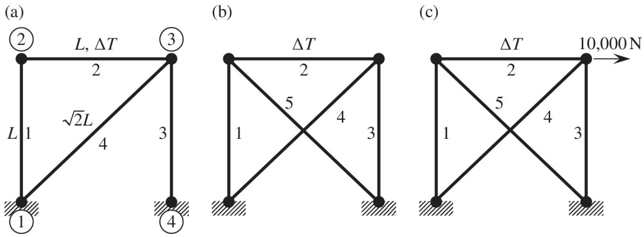
Use the finite element method to determine the nodal displacements in the plane truss shown in figure (a). The temperature of element 2 is 200°C above the reference temperature, that is,
Want to see the full answer?
Check out a sample textbook solution
Chapter 1 Solutions
Introduction To Finite Element Analysis And Design


- A copper wire, caliber 16 AWG (diameter of 0.1019 in.) 4 ft in length, is stretched with a force of 500 lb. It lengthens 0.21 in. and its diameter is reduced 0.10175 in. Determine the modulus of elasticity, from its response in 10^3 ksi.arrow_forwardA hand cranking lever, as shown in Figure 6 below, is used to start a truck engine byapplying a force F = 400 N. The material of the cranking lever has a yield strength = 320 MPa;Ultimate tensile strength = 500 MPa; Young’s modulus = 205 GPa; Modulus of rigidity = 84 GPaand poisson’s ratio = 0.3. Assuming factor of safety to be 4 based on yield strength, design thediameter of the lever at section X-X near the guide bush using: a) Maximum distortion energytheory; and b) Maximum shear stress theory.arrow_forwardIn a compound helical spring, the inner spring is concentric with the outer spring, but is 9 mm shorter. The outer spring has ten coils of mean diameter 24 mm, and the wire diameter is 3 mm. Find the stiffness of the inner spring if an axial load of 150 N causes the outer spring to compress 18 mm. If the mean coil diameter for the inner spring is 15.94 mm, find the wire diameter of the inner spring when it has eight coils. Both the springs are made of the same material having G = 77 GPa.arrow_forward
- Shown in the figure below is a parallel spring. If the allowable deformation is 25mm determine the value of P and the spring constant equivalentarrow_forward(PSD) A precision milling machine, weighing 4500 N, is supported on a rubber mount. The force-deflection relationship of the rubber mount is given by F = 270x + 0.25(x^3). Determine the equivalent linearized spring constant of the rubber mount at its static equilibrium position.arrow_forwardThere is a gap of δ = 0.05cm between the steel and copper bars seen in the figure. i) When the ambient temperature rises to 200oC, will there be a reaction force in the bearings? ii) If there is a reaction force, calculate the reaction forces RA and RB at points A and B. The cross-sectional area of both bars is equal and 5cm ^ 2. Materials;Modules of Elasticity: E Steel = 210 GPa E Copper = 120 GPa Expansion Coefficients: α Steel = 12.10-6 1 / 0C α Copper = 16.10-6 1 / 0Carrow_forward
- Figure Q4(a) shows the stress-strain curves of material A and material B. A circular rod of material A (diameter 3 cm, length 10 cm) is bonded to a circular rod of material B (diameter 4 cm, length 20 cm) as shown in Figure Q4(b). a) Based on the stress-strain curves shown determine the yield stress (σy) and the elastic modulus (E) of material A and material B.b) Assuming that the bond is rigid, determine the force P required to stretch the composite rod by 0.3 mm?c) Assuming a Poisson’s ratio value of 0.33, determine the change in diameter of the rod made from material B for the same P as determined in part (b).arrow_forwardFigure 1.29 shows the suspension system of a freight truck with a parallel-spring arrangement. Find the equivalent spring constant of the suspension if each of the three helical springs is made of steel with a shear modulus G = 100 GPaand has 10 effective turns, mean coil diameter D = 50 cm, and wire diameter d = 5 cmarrow_forwardFind the global stiffness matrix, displacement at node 1&2, reaction forces at 1&4, and force in spring for the following figure shown below. k1=90 N/mm, k2=1800 N/mm, k3=80 N/mm, P=600 N and u1=u4=0arrow_forward
- Determine the equivalent spring constant 20% A hoisting drum, carrying a steel wire rope, is mounted at the end of a cantilever beam as shown in the figure. Determine the equivalent spring constant of the system when the suspended length of the wire rope is /. Assume that the net cross-sectional diameter of the wire rope is d and the Young's modulus of the beam and the wire rope is E.arrow_forwardA closed-coil helical spring is to have stiffness of 900 N/m in compression with a maximum load of 45 N and a maximum shearing stress of 120 N/mm2.The length of the spring is 45 mm. find the wire diameter, mean coil radius and the number of coils. Take C= 40000 N/mm2arrow_forward4 helical springs is used in a suspension system of a motorcycle. The mean coil diameter is 15 cm, spring constant is 40,000 N/m, shear modulus = 80x10^9 N/(m^2), and has 8 effective turns. Determine what must be the wire diameter of the helical spring.arrow_forward
 Elements Of ElectromagneticsMechanical EngineeringISBN:9780190698614Author:Sadiku, Matthew N. O.Publisher:Oxford University Press
 Mechanics of Materials (10th Edition)Mechanical EngineeringISBN:9780134319650Author:Russell C. HibbelerPublisher:PEARSON
 Thermodynamics: An Engineering ApproachMechanical EngineeringISBN:9781259822674Author:Yunus A. Cengel Dr., Michael A. BolesPublisher:McGraw-Hill Education
 Control Systems EngineeringMechanical EngineeringISBN:9781118170519Author:Norman S. NisePublisher:WILEY
 Mechanics of Materials (MindTap Course List)Mechanical EngineeringISBN:9781337093347Author:Barry J. Goodno, James M. GerePublisher:Cengage Learning
 Engineering Mechanics: StaticsMechanical EngineeringISBN:9781118807330Author:James L. Meriam, L. G. Kraige, J. N. BoltonPublisher:WILEY